Question.
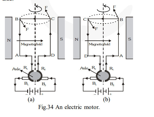
Draw a labelled diagram of an electric motor. Explain its principle and working. What is the function of a split-ring in an electric motor ?
Draw a labelled diagram of an electric motor. Explain its principle and working. What is the function of a split-ring in an electric motor ?
solution:
An electric motor is a rotating device that converts electrical energy to mechanical energy.
Principle involved : It is based on the fact that a current-carrying coil experiences equal and opposite forces on its edges which rotates it continuously.
Construction : An electric motor consists of a rectangular coil $\mathrm{ABCD}$ made of an insulated copper wire. The coil consists of large number of turns and it is wound on a soft iron core. The coil is placed between the two poles of a magnetic field such that the arms $\mathrm{AB}$ and $\mathrm{CD}$ are perpendicular to the direction of the magnetic field. The ends of the coil are connected to the two half-rings $R_{1}$ and $R_{2}$ called split rings. The inner sides of split rings are insulated and attached to an axle (not shown in figure). The external conducting edges of $R_{1}$ and $R_{2}$ touch two conducting stationary brushes (usually made of carbon) $B_{1}$ and $B_{2}$ respectively.
Working
(1) Current in the coil $\mathrm{ABCD}$ enters from the source battery through conducting brush $\mathrm{B}_{2}$ and flows back to the battery through brush $\mathrm{B}_{1} .$ The current in $\operatorname{arm} \mathrm{AB}$ of the coil flows from $B$ to $A$ and in arm CD it flows from D to C, that is, opposite to the direction of current through $\operatorname{arm} \mathrm{AB}$. That is the current flows along the vath DCBA.
(2) On applying Fleming's left hand rule, we find that the force acting on $\operatorname{arm} \mathrm{AB}$ pushes it upwards while the force acting on arm CD pushes it downwards. Thus, the coil and the axle, mounted free to turn about an axis, start rotating.
(3) After half rotation, $R_{2}$ makes contact with the brush $B_{1}$ and $R_{1}$ with brush $B_{2}$. Thus, the current in the coil gets reversed and flows along the path $\mathrm{ABCD}$. As a result, the directions of force acting on the two arms $\mathrm{AB}$ and $\mathrm{CD}$ are also reversed. The arm $\mathrm{AB}$ of the coil that was earlier pushed up is now pushed down and the arm CD previously pushed down is now pushed up. Due to this, the direction of rotation of the coil remains unchanged. The reversing of the current is repeated after every half rotation, giving rise to a continuous rotation of the coil and the axle.

The work of the split ring is to reverse the direction of current in the circuit. It acts as a commutator in the circuit. The reversal of current, reverses the direction of force acting on the two arms of the coil.
An electric motor is a rotating device that converts electrical energy to mechanical energy.
Principle involved : It is based on the fact that a current-carrying coil experiences equal and opposite forces on its edges which rotates it continuously.
Construction : An electric motor consists of a rectangular coil $\mathrm{ABCD}$ made of an insulated copper wire. The coil consists of large number of turns and it is wound on a soft iron core. The coil is placed between the two poles of a magnetic field such that the arms $\mathrm{AB}$ and $\mathrm{CD}$ are perpendicular to the direction of the magnetic field. The ends of the coil are connected to the two half-rings $R_{1}$ and $R_{2}$ called split rings. The inner sides of split rings are insulated and attached to an axle (not shown in figure). The external conducting edges of $R_{1}$ and $R_{2}$ touch two conducting stationary brushes (usually made of carbon) $B_{1}$ and $B_{2}$ respectively.
Working
(1) Current in the coil $\mathrm{ABCD}$ enters from the source battery through conducting brush $\mathrm{B}_{2}$ and flows back to the battery through brush $\mathrm{B}_{1} .$ The current in $\operatorname{arm} \mathrm{AB}$ of the coil flows from $B$ to $A$ and in arm CD it flows from D to C, that is, opposite to the direction of current through $\operatorname{arm} \mathrm{AB}$. That is the current flows along the vath DCBA.
(2) On applying Fleming's left hand rule, we find that the force acting on $\operatorname{arm} \mathrm{AB}$ pushes it upwards while the force acting on arm CD pushes it downwards. Thus, the coil and the axle, mounted free to turn about an axis, start rotating.
(3) After half rotation, $R_{2}$ makes contact with the brush $B_{1}$ and $R_{1}$ with brush $B_{2}$. Thus, the current in the coil gets reversed and flows along the path $\mathrm{ABCD}$. As a result, the directions of force acting on the two arms $\mathrm{AB}$ and $\mathrm{CD}$ are also reversed. The arm $\mathrm{AB}$ of the coil that was earlier pushed up is now pushed down and the arm CD previously pushed down is now pushed up. Due to this, the direction of rotation of the coil remains unchanged. The reversing of the current is repeated after every half rotation, giving rise to a continuous rotation of the coil and the axle.

The work of the split ring is to reverse the direction of current in the circuit. It acts as a commutator in the circuit. The reversal of current, reverses the direction of force acting on the two arms of the coil.
Click here to get exam-ready with eSaral
For making your preparation journey smoother of JEE, NEET and Class 8 to 10, grab our app now.
