Alternating Current - JEE Advanced Previous Year Questions with Solutions

JEE Advanced Previous Year Questions of Physics with Solutions are available at eSaral. Practicing JEE Advanced Previous Year Papers Questions of Physics will help the JEE aspirants in realizing the question pattern as well as help in analyzing weak & strong areas.
Get detailed Class 11th & 12th Physics Notes to prepare for Boards as well as competitive exams like IIT JEE, NEET etc.
eSaral helps the students in clearing and understanding each topic in a better way. eSaral is providing complete chapter-wise notes of Class 11th and 12th both for all subjects.
Click Here for JEE main Previous Year Topic Wise Questions of Physics with Solutions
Download eSaral app for free study material and video tutorials.
Paragraph for Questions 6 and 7
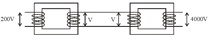
A thermal power plant produces electric power of 600 kW and 4000 V, which is to be transported to a place 20 km away from the power plant for consumers' usage. It can be transported either directly with a cable of large current carrying capacity or by using a combination of step-up and step-down transformers at the two ends. The drawback of the direct transmission is the large energy dissipation. In the method using transformers, the dissipation is much smaller. In this method, a step-up transformer is used at the plant side so that the current is reduced to a smaller value. At the consumers' end, a step-down transformer is used to supply power to the consumers at the specified lower voltage. It is reasonable to assume that the power cable is purely resistive and the transformers are ideal with a power factor unity. All the currents and voltages mentioned are rms values.
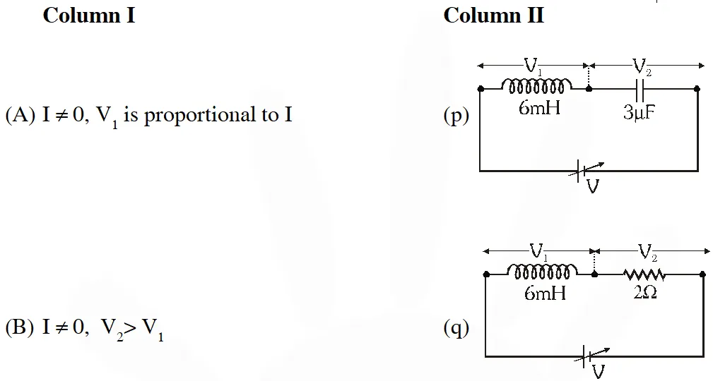
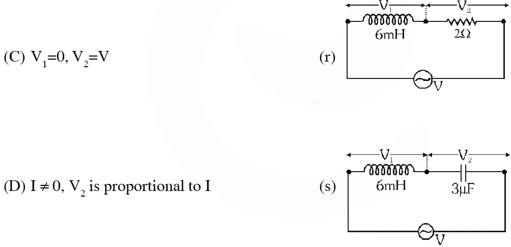
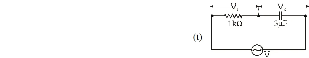
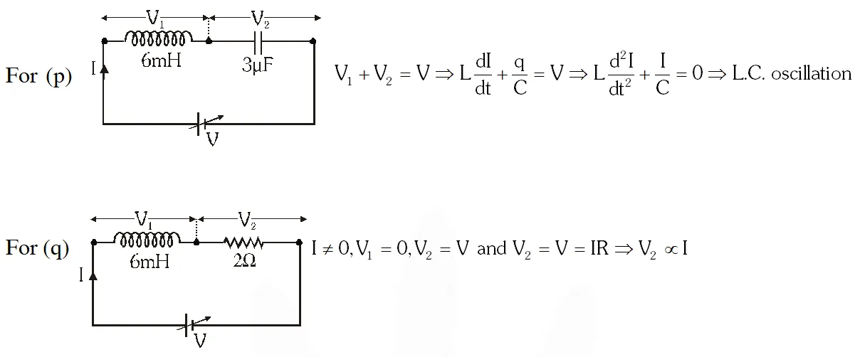
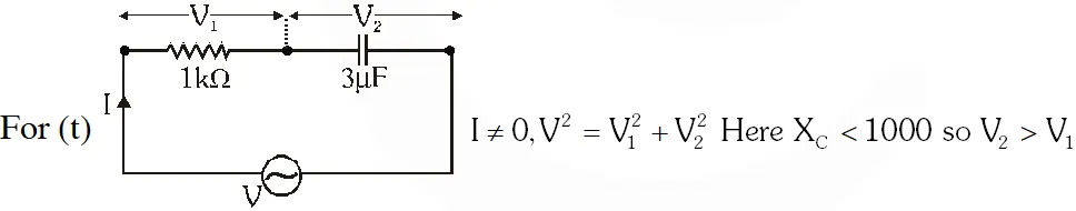
Q. You are given many resistances, capacitors and inductors. These are connected to a variable DC voltage source (the first two circuits) or an AC voltage source of 50 Hz frequency (the next three circuits) in different ways as shown in Column II. When a current I (steady state for DC or rms for AC) flows through the circuit, the corresponding voltage $\mathrm{V}_{1}$ and $\mathrm{V}_{2}$ (indicated in circuits) are related as shown in Column I. Match the two
 [JEE 2010]
[JEE 2010]
Ans. (A) RST (B) QRST (C) PQ (D) QRST

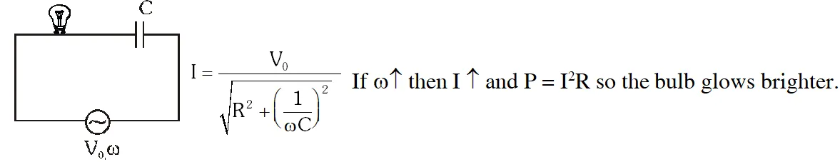
Q. An AC voltage source of variable angular frequency and fixed amplitude $\mathrm{V}_{0}$ is connected in series with a capacitance C and an electric bulb of resistance R (inductance zero). When $\omega$ is increased
(A) the bulb glows dimmer
(B) the bulb glows brighter
(C) total impedance of the circuit is unchanged
(D) total impedance of the circuit increases
[JEE 2010]
Ans. (B)
Q. A series R-C circuit is connected to AC voltage source. Consider two cases ; (A) when C is without a dielectric medium and (B) when C is filled with dielectric of constant 4. The current $\mathrm{I}_{\mathrm{R}}$ through the resistor and voltage $\mathrm{V}_{\mathrm{c}}$ across the capacitor are compared in the two cases. Which of the following is/are true?
(A) $I_{R}^{A}>I_{R}^{B}$
$(\mathrm{B}) \quad I_{R}^{A}V_{c}^{B}$
(D) $V_{C}^{A} [JEE 2011]
Ans. (B,C)
$\mathrm{x}_{\mathrm{c}}$ decreases therefore impedence decreases and current increases. $\mathrm{I}_{\mathrm{B}}>\mathrm{I}_{\mathrm{A}}$
As $\mathrm{I}_{\mathrm{B}}$ increases the voltage across ‘R’ increases therefore $\mathrm{V}_{\mathrm{c}}$ decreases.
Q. A series R-C combination is connected to an AC voltage of angular frequency $\omega=500$radian/s. If the impedance of the R-C circuit is $R \sqrt{1.25}$, the time constant (in millisecond) of the circuit is ?
[JEE 2011]
Ans. 4
$1.25 \mathrm{R}^{2}=\mathrm{R}^{2}+\left(\frac{1}{\omega c}\right)^{2}$
$0.25 \mathrm{R}^{2}=\left(\frac{1}{\omega c}\right)^{2} ; 0.5 \mathrm{R}=\frac{1}{500 \times C} ; \mathrm{C}=\frac{1}{250 R} ; \mathrm{RC}=\frac{1}{250} \mathrm{sec}$
$\tau=4$ millisecond; $\tau=4$
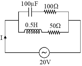
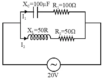
Q. In the given circuit, the AC source has $\omega=100 \mathrm{rad} / \mathrm{s}$. Considering the inductor and capacitor to be ideal, the correct choice (s) is(are)
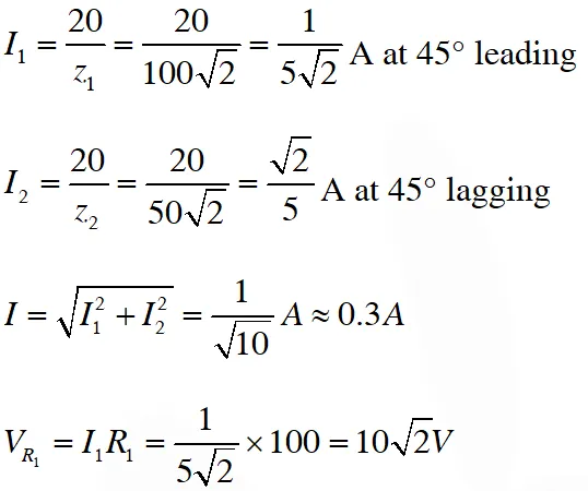
(A) The current through the circuit, I is $0.3 \mathrm{A}$.
(B) The current through the circuit, is $0.3 \sqrt{2 \mathrm{A}}$
(C) The voltage across $100 \Omega$ resistor $=10 \sqrt{2} \mathrm{V}$
(D) The voltage across $50 \Omega$ resistor $=10 \mathrm{V}$
 [JEE 2012]
[JEE 2012]
Ans. (C or A,C)
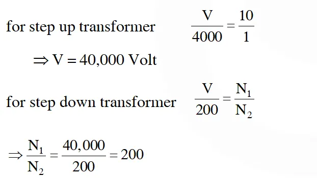
Q. In the method using the transformers, assume that the ratio of the number of turns in the primary to that in the secondary in the step-up transformer is 1 : 10. If the power to the consumers has to be supplied at 200 V, the ratio of the number of turns in the primary to that in the secondary in the step-down transformer is
(A) 200 : 1
(B) 150 : 1
(C) 100 : 1
(D) 50 : 1
[JEE Advance-2013]
Ans. (A)
Q. If the direct transmission method with a cable of resistance 0.4 W km–1 is used, the power dissipation (in %) during transmission is
(A) 20
(B) 30
(C) 40
(D) 50
[JEE Advance-2013]
Ans. (B)
Current in transmission line $=\frac{\text { Power }}{\text { Voltage }}$
$=\frac{600 \times 10^{3}}{40,000}=150 \mathrm{A}$
Resistance of line $=0.4 \times 20=8 \Omega$
Power loss in line $=\mathrm{i}^{2} \mathrm{R}=(150)^{2} 8$
$=180 \mathrm{KW}$
percentage of power dissipation in during transmission $=\frac{1800 \times 10^{3}}{600 \times 10^{3}} \times 100=30 \%$
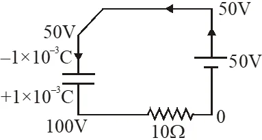
Q. At time t = 0, terminal A in the circuit shown in the figure is connected to B by a key and an alternating current $\mathrm{I}(\mathrm{t})=\mathrm{I}_{0} \cos (\omega \mathrm{t})$,with I0 = 1A and $\omega=500 \mathrm{rad} \mathrm{s}^{-1}$ starts flowing in it with the initial direction shown in the figure. At $=\frac{7 \pi}{6 \omega}$, the key is switched from B to D. Now onwards only A and D are connected. A total charge Q flows from the battery to charge the capacitor fully. If $\mathrm{C}=20 \mu \mathrm{F}, \mathrm{R}=10 \Omega$ and the battery is ideal with emf of 50 V, identify the correct statement (s).
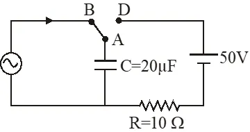 (A) Magnitude of the maximum charge on the capacitor before $\mathrm{t}=\frac{7 \pi}{6 \omega}$ is $1 \times 10^{-3} \mathrm{C}$
(B) The current in the left part of the circuit just before $\mathrm{t}=\frac{7 \pi}{6 \omega}$ is clockwise.
(C) Immediately after A is connected to D, the current in $\mathrm{R}$ is $10 \mathrm{A}$
(D) $\mathrm{Q}=2 \times 10^{-3} \mathrm{C}$
[JEE Advance-2014]
(A) Magnitude of the maximum charge on the capacitor before $\mathrm{t}=\frac{7 \pi}{6 \omega}$ is $1 \times 10^{-3} \mathrm{C}$
(B) The current in the left part of the circuit just before $\mathrm{t}=\frac{7 \pi}{6 \omega}$ is clockwise.
(C) Immediately after A is connected to D, the current in $\mathrm{R}$ is $10 \mathrm{A}$
(D) $\mathrm{Q}=2 \times 10^{-3} \mathrm{C}$
[JEE Advance-2014]
Ans. (C,D)
Current $\mathrm{I}=\mathrm{I}_{0} \cos (\omega \mathrm{t})$
$\frac{\mathrm{d} q}{\mathrm{dt}}=\mathrm{I}_{0} \cos (\omega \mathrm{t})$
$\Rightarrow \mathrm{q}=\frac{\mathrm{I}_{0}}{\omega} \sin (\omega \mathrm{t})$
$\Rightarrow \mathrm{q}=\frac{1}{500} \sin (\omega \mathrm{t})$
$\Rightarrow \mathrm{q}=\left(2 \times 10^{-3}\right) \sin (\omega \mathrm{t})$
So, maximum charge $=2 \times 10^{-3} \mathrm{C}$
immediately before $\mathrm{t}=\frac{7 \pi}{6 \omega}$
Current in left part just before $\mathrm{t}=\frac{7 \pi}{6 \omega}$
$\mathrm{I}=\mathrm{I}_{0} \cos \left(\omega \times \frac{7 \pi}{6 \omega}\right)=-\frac{\mathrm{I}_{0} \sqrt{3}}{2}$
Since current is negative hence current will be anticlockwise.
immediately after $\mathrm{t}=\frac{7 \pi}{6 \omega}$
$\mathrm{q}=\left(2 \times 10^{-3}\right) \sin \left(\omega \times \frac{7 \pi}{6 \omega}\right)$
$\mathrm{q}=\left(2 \times 10^{-3}\right) \sin \left(\omega \times \frac{7 \pi}{6 \omega}\right)$
$=-1 \times 10^{-3} \mathrm{C}$
Current in $10 \Omega$ resistance,
$\mathrm{I}=\frac{100}{10}=10 \mathrm{A}$
At steady state, potential difference of capaictor is same as of battery,
So, final charge is
$\mathrm{Q}_{\mathrm{f}}=\mathrm{C} \varepsilon=(20 \mu \mathrm{F})(50 \mathrm{V})=+1 \times 10^{-3} \mathrm{C}$
change in charge $=+10^{-3}-\left(-10^{-3}\right)=2 \times 10^{-3} \mathrm{C}$
Q. In the circuit shown, $\mathrm{L}=1 \mu \mathrm{H}, \mathrm{C}=1 \mu \mathrm{F}$ and $\mathrm{R}=1 \mathrm{k} \Omega$.They are connected in series with an a.c. source $\mathrm{V}=\mathrm{V}_{0}$ $\sin \omega t$ as shown. Which of the following options is/are correct ?
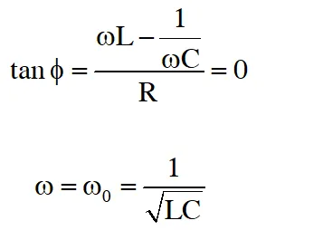
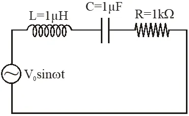 (A) The frequency at which the current will be in phase with the voltage is independent of R.
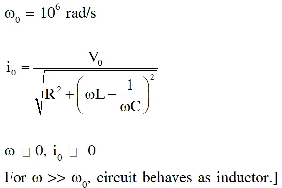
(B) At $\omega \sim 0$ the current flowing through the circuit becomes nearly zero
(C) At $\omega>>10^{6}$ rad.s $^{-1},$ the circuit behaves like a capacitor.
(D) The current will be in phase with the voltage if $\omega=10^{4} \mathrm{rad.s}^{-1}$
[JEE Advance-2017]
(A) The frequency at which the current will be in phase with the voltage is independent of R.
(B) At $\omega \sim 0$ the current flowing through the circuit becomes nearly zero
(C) At $\omega>>10^{6}$ rad.s $^{-1},$ the circuit behaves like a capacitor.
(D) The current will be in phase with the voltage if $\omega=10^{4} \mathrm{rad.s}^{-1}$
[JEE Advance-2017]
Ans. (A,B)
Q. The instantaneous voltages at three terminals marked X, Y and Z are given by $\mathrm{V}_{\mathrm{x}}=\mathrm{V}_{0} \sin$
$\omega \mathrm{t} \mathrm{V}_{\mathrm{Y}}=\mathrm{V}_{0} \sin \left(\omega \mathrm{t}+\frac{2 \pi}{3}\right)$ and $\mathrm{V}_{\mathrm{Z}}=\mathrm{V}_{0} \sin \left(\omega \mathrm{t}+\frac{4 \pi}{3}\right)$
An ideal voltmeter is configured to read rms value of the potential difference between its terminals. It is connected between points X and Y and then between Y and Z. The reading(s) of the voltmeter will be:-
(A) $\mathrm{V}_{\mathrm{XY}}^{\mathrm{rms}}=\mathrm{V}_{0}$
(B) $\quad \mathrm{V}_{\mathrm{YZ}}^{\mathrm{ms}}=\mathrm{V}_{0} \sqrt{\frac{1}{2}}$
(C) Independent of the choice of the two terminals
(D) $\quad V_{\mathrm{XY}}^{\mathrm{ms}}=\mathrm{V}_{0} \sqrt{\frac{3}{2}}$
[JEE Advance-2017]
Ans. (C,D)
Potential difference between $X \& Y=V_{X}-V_{Y}$
Potential difference between $\mathrm{Y} \& \mathrm{Z}=\mathrm{V}_{\mathrm{Y}}-\mathrm{V}_{7}$
Phasor of the voltages :
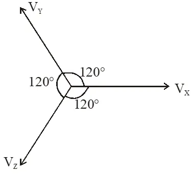 $\therefore \mathrm{V}_{\mathrm{X}}-\mathrm{V}_{\mathrm{Y}}=\sqrt{3} \mathrm{V}_{0}$
$\mathrm{V}_{\mathrm{XY}}^{\mathrm{ms}}=\frac{\sqrt{3} \mathrm{V}_{0}}{\sqrt{2}}$
similarly $\mathrm{V}_{\mathrm{YZ}}^{\mathrm{ms}}=\frac{\sqrt{3} \mathrm{V}_{0}}{\sqrt{2}}$
Also difference is independent of choice of two terminals.
$\therefore \mathrm{V}_{\mathrm{X}}-\mathrm{V}_{\mathrm{Y}}=\sqrt{3} \mathrm{V}_{0}$
$\mathrm{V}_{\mathrm{XY}}^{\mathrm{ms}}=\frac{\sqrt{3} \mathrm{V}_{0}}{\sqrt{2}}$
similarly $\mathrm{V}_{\mathrm{YZ}}^{\mathrm{ms}}=\frac{\sqrt{3} \mathrm{V}_{0}}{\sqrt{2}}$
Also difference is independent of choice of two terminals.