eSaral › Class 12 ›Current Electricity Class 12 Problems with Solutions:Important Questions for Exams

Why Current Electricity Problems Matter for Class 12 Exams
Current Electricity is one of the highest-weightage chapters in Class 12 Physics — both for CBSE board exams and competitive exams like JEE Main and NEET. According to the NTA's official JEE Main syllabus, this chapter accounts for 2–3 questions per paper consistently.
Students who struggle with Current Electricity typically make one of three mistakes: memorising formulas without understanding derivations, skipping unit analysis, or ignoring circuit diagrams. This guide solves all the important NCERT-based problems stepwise, so you understand the logic behind every answer — not just the final number
India's Best Exam Preparation for Class 12th - Download Now
Q. What happens to the drift velocity $v_{\mathrm{d}}$ of electron and to the resistance $R,$ if length of the conductor is doubled (keeping potential difference unchanged) $?$
Ans. Drift velocity is $v_{d}=\frac{e E \tau}{m}=\frac{e V \tau}{m l}$ and $R=\rho 1 / \mathrm{A}$ Thus, (i) When l is doubled, drift velocity becomes half of the initial value. (ii) When l is doubled, resistance becomes twice the initial value.
Q. A low voltage supply from which one needs high currents must have very low internal resistance. Why ? [NCERT]
Ans. since the maximum current drawn from a source $\quad(\text { cell }), I=\frac{E}{r} |$ Hence, for low value of $r$, current $I$ will be high.
Q. Is there a net field inside the cell when the circuit is closed and a steady current passes through? Explain. [NCERT]
Ans. When circuit is closed from outside, current flows in the direction of electrostatic field outside, and opposite to the direction of electrostatic field inside the cell. The latter fact shows that there is a net field inside the cell opposite to the electrostatic field
Q. A high tension (HT) supply of say, $6 k V$ must have a very large internal resistance. Why? [NCERT]
Ans. If the circuit is shorted (accidentally), the current drawn will exceed the safety limits in case internal resistance is not large.
Q. In a potentiometer arrangement, a cell of emf 1.25 V gives a balance point at 35.0 cm length of the wire. If the cell is replaced by another cell and the balance point shifts to 63.0 cm, what is the emf of the second cell ? [NCERT]
Ans. Here, $E_{1}=1.25 \mathrm{V} ; l_{1}=35.0 \mathrm{cm} ; l_{2}=63.0 \mathrm{cm}$ $\quad$ Now $, \frac{E_{1}}{E_{2}}=\frac{l_{1}}{l_{2}}$ Or $E_{2}=E_{1} \times \frac{l_{2}}{l_{1}}=1.25 \times \frac{63.0}{35.0}=2.25 \mathrm{V}$
Q. A galvanometer coil has a resistance of and the metre shows full scale deflection for a current of 4 mA. How will convert the metre into an ammeter of range 0–6 A. [NCERT]
Ans. By using a shunt of value,
Q. A galvanometer coil has a resistance of and the metre shows full scale deflection for a current of 3 mA. How will you convert the metre into an voltmeter of range 0 to 18 V ? [NCERT]
Ans. By connecting a resistance in series $R=\frac{V}{I_{S}}-G=\frac{18}{3 \times 10^{-3}}-12=(6000-12) \Omega=5988 \Omega$
Q. The electrons drift speed is estimated to be only a few $m m s^{-1}$for currents in range of a few ampere. How then is current established almost the instant a circuit is closed ? [NCERT]
Ans. When we close the circuit, the electric field is established in the circuit instantly with the speed of electrons to flow from one end of the conductor to another end. It means, the information for the flow of current is transmitted through the propagation of electromagnetic waves (electric impulse) and not with drift velocity of the electrons.
Q. When electrons drift in a metal from lower to higher potential, does it mean that all the ‘free’ electrons of the metal are moving in the same direction ? [NCERT]
Ans. When a potential difference is applied across the two ends of a metal conductor, the drifting of free electrons takes place from lower to higher potential. These drifting electrons also have thermal velocity. At an instant, each free electrons moves in a direction of resultant velocity of its thermal velocity and drift velocity, which is different for various free electrons. Hence all the free electrons in the metal conductor are not moving in the same direction.
Q. Currents of the order of 0.1 A, through the human body are fatal. What causes the Death :heating of the body due to electric current or some thing else ? [NCERT]
Ans. The cause of death of a person can not be heating. The person may receive burns if the currents are too large. The cause of death is the interference caused by external currents with the nerve processes related to our heart beating, which is basically electrical in nature. Beyond a certain limit, this interference is fatal.
Q. Choose correct alternative (a) Alloys of metals usually have (greater/less) resistivity than that of their constituent metals (b) Alloys usually have much (lower/higher) temperature coefficients of resistance than pure metals. (c) The resistivity of the alloy manganin is nearly independent of/increases rapidly with increase of temperature. (d) The resistivity of a typical insulator (e.g. amber) is greater than that of a metal by a factor of the order of $\left(10^{22} / 10^{3}\right)$ [NCERT]
Ans. (a) Greater (b) Lower (c) Nearly independent of (d) $10^{22}$
Q. A silver wire has a resistance of $2.1 \Omega$ at $27.5^{\circ} \mathrm{C},$ and a resistance of $2.7 \Omega$ at $100^{\circ} \mathrm{C}$. Determine the temperature coefficient of resistivity of silver? [NCERT]
Ans. $R_{t}=R_{0}(1+\alpha t) \mathbf{P} R_{27.5}=R_{0}(1+27.5 \alpha)$ and $R_{100}=R_{0}(1+100 \alpha)$ $R_{27.5}=2.1 \Omega$ and $R_{100}=2.7 \Omega$ hence $\frac{1+100 \alpha}{1+27.5 \alpha}=\frac{2.7}{2.1}$ On solving we get
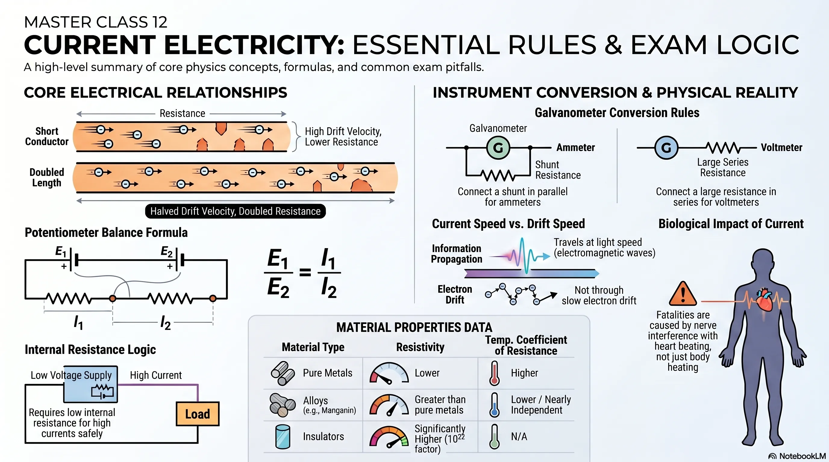
Q. A heating element using nichrome connected to a 230 V supply draws an initial current of 3.2 A which settles after a few seconds to a steady value of 2.8 A. What is the steady temperature of the heating element if the room temperature is $27.0^{\circ} \mathrm{C}$? Temperature coefficient of resistance of nichrome averaged over the temperature range involved is $1.70 \times 10^{-4} \circ C^{-1}$ [NCERT]
Ans. When a heating element is connected to a supply, initial value of current is slightly higher than the steady value. This is so because of heating resistance of the element increases and value of current decreases. When a steady state is reached
i.e. heat produced is equal to heat lost to the surrounding. Temperature will not rise further.
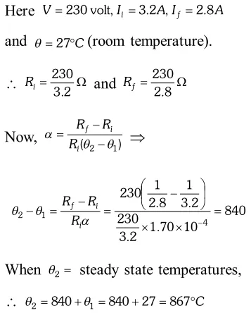
Q. The number density of conduction electrons in a copper conductor estimated is $8.5 \times 10^{28} \mathrm{m}^{-3}$. How long does an electron take to drift from one end of a wire 3.0m long to its to its other end ? The area of cross-section of the wire is $2.0 \times 10^{-6} \mathrm{m}^{2}$ and it is carrying a current of 3.0A. [NCERT]
Ans. Here, $n=8.5 \times 10^{28} \mathrm{m}^{-3} ; \quad l=3.0 \mathrm{m} ; \quad A=2.0 \times 10^{-6} \mathrm{m}^{2}$ $I=3.0 \mathrm{A}, t=?$ 
Q. A cell of
emf 1.5
V and internal resistance is connected to a (non-linear) conductor whose
V–I graph is shown in figure. Obtain graphically the current drawn from the cell and its terminal voltage.
[NCERT] 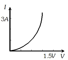
Ans. We know that, $V=E-I r, \quad E=1.5$ volt, $r=0.5 \Omega$
$$ I r=E-V, 0.5 I=1.5-V $$ Values of V and I satisfying above equation are V (volt) I (ampere) 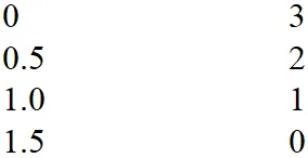 Graph of these values is a line represented by dotted lines. There is a common point between the dotted line and the graph given. This corresponds to 1volt and 1A. So, the cell given supplies 1A current for 1volt.
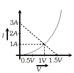
Q. A battery of
emf 9
V and negligible internal resistance is connected to a $3 k \Omega$ resistor. The potential drop heross a part of the resistor (between point $A$ and $B$ in figure) is measured by (i) a $20 \mathrm{k} \Omega$ voltmeter. (ii) a $1 \mathrm{k\Omega}$ voltmeter. and (iii) both the voltmeters are connected across $A B .$ In which case would you get the (i) highest, (ii) lowest reading?
[NCERT] 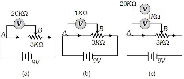
Ans. The voltmeter, which will draw minimum current (so that potential difference across AB decrease by a minimum amount), will give the highest reading. In case $(a), R_{V}=20 k \Omega$ In case $(b), R_{V}=1 k \Omega$ In case $(c), \frac{1}{R_{V}}=\frac{1}{20}+\frac{1}{1}=\frac{1+20}{20}$ or $R_{V}=\frac{20}{21} k \Omega$ (i) Since in case $(a)$, the resistance of voltmeter is maximum ( $20 k \Omega$ ) ; it will draw minimum current and hence it will give the maximum reading. (ii) Since in case $(c), R_{\mathrm{v}}$ is minimum $\left(\frac{20}{21} k \Omega\right),$ it will give lowest reading.
Q. Storage battery of a car has an emfof 12 V. If the internal resistance of the battery is $0.4 \Omega,$ what is the maximum current that can be drawn from the battery ? [NCERT]
Ans. Maximum current is drawn when external resistance is zero
i.e. 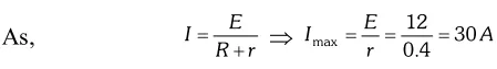
Q. Six lead-acid type of secondary cells each of emf 2.0 V and internal resistance $0.015 \Omega$ are joined in series to provide a supply to a resistance of $8.5 \Omega$ What are the current drawn from the supply and its terminal voltage ? [NCERT]
Ans. Total emf of the combination $=6 \times 2 V=12$ volt Total internal resistance $=6 \times 0.015 \Omega=0.09 \Omega$ External resistance of the circuit $=8.5 \Omega$ Total resistance of the circuit $=8.5+0.09=8.59 \Omega$ Current drawn, $I=\frac{12}{8.59}=1.4 A$ Terminal potential difference, $\mathrm{V}=12-1.4 \times 0.09$ $=12-0.126=11.9$ volt
Q. A secondary cell after long the use has an emf of 1.9 V and a large internal resistance $380 \Omega$ of What maximum current can be drawn from the cell ? Could the cell drive the starting motor of a car ?
Ans. Maximum current $=\frac{1.9}{380}=0.005 A,$ A large current is required by a motor starter for a few second. So it cannot be used in a car.
Q. Two identical cells of emf 1.5 V each joined in parallel provide supply to an external circuit consisting of two resistors of each joined in parallel. A very high resistance voltmeter reads the terminal voltage of the cells to be 1.4 V. What is the internal resistance of each cell? [NCERT]
Ans. In parallel combination of cells, net emf is equal to the emf of either cell. i.e. volt If $^{c} r^{,}$ is internal resistance of each cell, then $\frac{1}{r_{P}}=\frac{2}{r}$ P $r_{P}=0.5 r$ External resistance is $R_{P}=\frac{17}{2} \Omega=8.5 \Omega$ Terminal potential difference $V=1.4$ volt $r_{P}=\frac{E-V}{V} R_{P}$. $\mathrm{B}$. $5 r-\frac{1.5-1.4}{1.4} \times 8.5$ $\mathrm{B} \quad r=\frac{17}{14} \Omega=1.2 \Omega$
Q. (a) A d.c. supply of 120 V is connected to a large resistance X. A voltmeter of resistance 10 kW placed in series in the circuit reads 4 V. What is the value of X ? (b) What do you think is the purpose in using a voltmeter, instead of an ammeter, to determine the large resistance X ? [NCERT]
Ans. 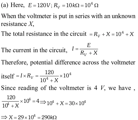 (b) If an ammeter is used, then its reading will be too small to be measured.
 Q. A galvanometer with a coil of resistance $12.0 \Omega$ shows a full scale deflection for a current of 2.5 mA. How will you convert the galvanometer into (a) an ammeter of range 0 to 7.5 A, (b) a voltmeter of range 0 to 10.0 V ? Determine the net resistance of the metre in each case. When an ammeter is put in a circuit, does it read (slightly) less or more than the actual current in the original circuit ? When a voltmeter is put across a part of the circuit, does it read (slightly) less or more than the original voltage drop ? Explain. [NCERT]
Ans. 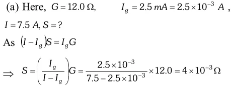
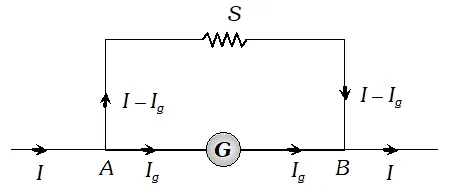 Now, the resistance (R) of the ammeter will be
 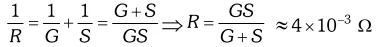 As ammeter is used in series with the circuit, therefore, its presence will increase slightly the effective resistance of the circuit and hence will decrease the current. Therefore, the ammeter put in the circuit will read slightly less. (b) For conversion into voltmeter, let R be the resistance in series with galvanometer. As $\quad R=\frac{V}{I_{g}}-G$
 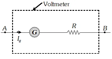 $\backslash R=\frac{10}{2.5 \times 10^{-3}}-12=4000-12=3988 \Omega$ $\therefore \quad$ Net $\quad$ resistance of $\quad$ the voltmeter $=3988+12=4000 \Omega$ A voltmeter is used in parallel with the circuit. It will also allow some current to pass through it. Due to it, the current in the circuit across the two points where voltmeter is connected decreases and hence potential difference decreases. Therefore, the voltmeter reads slightly less value.
 Q. A voltmeter reads 5.0 V at full scale deflection and is graded according to its resistance per volt at full scale deflection as $5000 \Omega / V$ How will you convert it into a voltmeter that reads 20 V at full scale deflection ? Will it still be graded as $5000 \Omega / V$? Will you prefer this voltmeter to one that is graded as $2000 \Omega / V ?$? [NCERT]
Ans. Resistance per volt at full scale deflection $=5000 \Omega V^{-1}$ Reading of voltmeter at full scale deflection $=5 V$ Hence, resistance of galvanometer, $G=5000 \times 5=25000 \Omega$ and current flowing for full scale deflection, $I_{g}=\frac{1 \mathrm{V}}{5000 \Omega}=0.0002 \mathrm{A}$ The given metre work as voltmeter for range upto $20 V,$ if a resistance $R$ is connected in series with it of value, $R=\frac{V}{I_{g}}-G=\frac{20}{0.0002}-25000$ $\mathrm{B} R=75000 \Omega$ Hence, total resistance of the new voltmeter $=$ $75000+25000=10^{5} \Omega$ and new grading (i.e. resistance per volt) $\frac{10^{5}}{20}=5000 \Omega V^{-1}$
Q. You are given two resistors
X and
Y whose resistances are to be determined using an ammeter of resistance $0.5 \Omega$ and a voltmeter of resistance $20 \times 10^{3} \Omega$ It is known that
X is in the range of a few ohms, while
Y is in the range of several thousand ohms. In each case, which of the following two connections would you choose for the measurement of resistance ?
[NCERT] 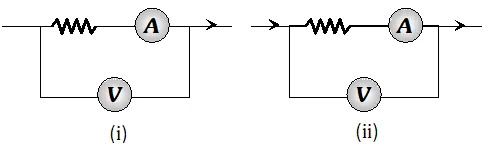
Ans. (i) For resistance X is small; (ii) Circuit should be used to measure it. As $\quad$ Resistance $(X)=\frac{\text { Reading of } V}{\text { Reading of } A}$ In circuit (i) it will affect the reading of ammeter. For resistance X is very large, (i) circuit should be used to measure it. As resistance Y is very large in comparison to the resistance of ammeter, it does not affect the reading of ammeter.
Q. The earth’s surface has a negative surface charge density of $10^{-9} \mathrm{Cm}^{ 2}$ . The potential difference of 400kV between the top of the atmosphere and the surface results (due to low conductivity of the lower atmosphere) in current of only 1800A over the entire globe. If there were no mechanism of sustaining atmospheric electric field; how much time (roughly) would be required to neutralise (because there is a mechanism to replenish electric charges namely the continual thunder storms and lightning in different parts of the globe) Radius of the earth$=6.37 \times 10^{6} \mathrm{m}$ [NCERT]
Ans. Here, $r=6.37 \times 10^{6} \mathrm{m} ; \sigma=10^{-9} \mathrm{Cm}^{-2} ; I=1800 \mathrm{A}$
Area of the globe, $A=4 \pi^{2}=4 \times 3.14 \times\left(6.37 \times 10^{6}\right)^{2}=509.64 \times 10^{12} \mathrm{m}^{2}$ 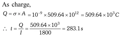
Q. (a) Estimate the average drift speed of conduction electrons in a copper wire of cross sectional area $1.0 \times 10^{-7} \mathrm{m}^{2}$ carrying a current of 1.5 A. Assume that each copper atom constributes roughly one conduction electron. The density of copper is $9.0 \times 10^{3} \mathrm{kg} / \mathrm{m}^{3}$and its atomic mass is $63.5 u$ (b) Compare the drift speed of obtained above with, (i) Thermal speeds of copper atoms at ordinary temperatures. (ii) Speed of propagation of electric field along the conductor which causes the drift motion. [NCERT]
Ans. (a) The direction of drift velocity of conduction electrons is opposite to the electric field direction,
i.e., electrons drift in the direction of increasing potential. The drift speed $v_{d}$ is given by equation
$v_{d}=\frac{1}{n e A}$ Now, $e=1.6 \times 10^{-19} \mathrm{C}, A=1.0 \times 10^{-7} \mathrm{m}^{2}, \mathrm{I}=1.5 \mathrm{A}$. The density of conduction electrons, $n$ is equal to the number of atoms per cubic metre (assuming one conduction electron per $C u$ atom as is responsible from its valence electron count of one). Acubic metre of copper has mass of $9.0 \times 10^{3} \mathrm{kg}$. Since $6.0 \times 10^{23}$ copper atoms have a mass of $63.5 \mathrm{g} .$ 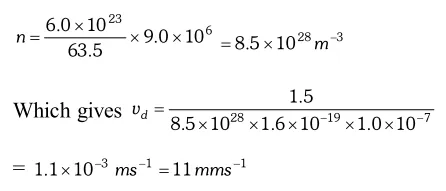 (b) (i) At a temperature $T$, the thermal speed of a copper atom of mass $M$ is obtained from [ $\left.<(1 / 2) M v^{2}>=(3 / 2) k_{B} T\right]$ and is thus typically of the order of $\sqrt{k_{B} T / M},$ where $k_{B}$ is the Boltzmann constant. For copper at $300 K,$ this is about $2 \times 10^{2} m / s .$ This figure indicates the random vibrational speeds of electrons is much smaller, about $10^{-5}$ times the typical thermal speed at ordinary temperatures. (ii) An electric field travelling along the conductor has a speed of an electromagnetic wave, namely equal to $3.0 \times 10^{8} \mathrm{ms}^{-1}$. The drift speed is in comparison, extremely small, smaller by a factor of $10^{-11}$.
 Q. 4 cells of identical
emf E, internal resistance
r, are connected in series to a variable resistor. The following graph shows the variation of terminal voltage of the combination with the current output
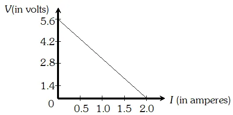
Ans. When $I=0,$ total emf = terminal voltage $\backslash 4 E=5.6 \mathrm{V}$ or $E=1.4 \mathrm{V}$ When $I=1.0 \mathrm{A}, \mathrm{V}=\frac{2.8}{4}=0.7$ Internal resistance, $r=\frac{E-V}{I}=\frac{1.4-0.7}{1.0}=0.7 \Omega$ The output power is maximum, when external resistance = internal resistance = 4r
Q. Determine the current in each branch of the network shown in figure
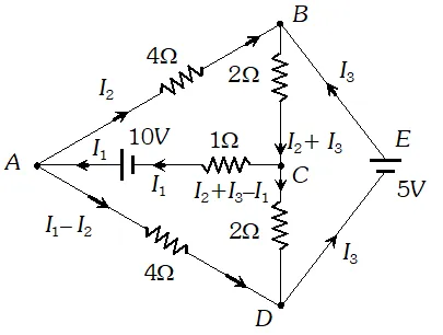
Ans. Each branch of the network is assigned an unknown current to be determined by the application of Kirchhoff’s rules. To reduce the number of unknowns at the outset, the first rule of Kirchhoff is used at every junction to assign the unknown current in each branch. We then have three unknowns $I_{1}, I_{2}$ and $I_{3}$ which can be found by applying the second rule of Kirchhoff to three different closed loops. Kirchhoff’s second rule for the closed loop ADCA gives. $10-4\left(I_{1}-I_{2}\right)+2\left(I_{2}+I_{3}-I_{1}\right)-I_{1}=0$ …(i) that is, $7 I_{1}-6 I_{2}-2 I_{3}=10$ For the closed loop $A B C A,$ we get $10-4 I_{2}-2\left(I_{2}+I_{3}\right)-I_{1}=0$ that is, $I_{1}+6 I_{2}+2 I_{3}=10$ …(ii) For the closed loop $B C D E B,$ we get $5-2\left(I_{2}+I_{3}\right)-2\left(I_{2}+I_{3}-I\right)=0$ that is, $21_{1}-4 I_{2}-4 I_{3}=-5$ …(iii) Equations (i), (ii) and (iii) are three simultaneous equations in three unknowns. These can be solved by the usual method to give $I_{1}=2.5 A, \quad I_{2}=\frac{5}{8} A, \quad I_{3}=1 \frac{7}{8} A$ The currents in the various branches of the network are $A B: \frac{5}{8} A, C A: 2 \frac{1}{2} A, D E B: 1 \frac{7}{8} A$ $A D: 1 \frac{7}{8} A, C D: 0 A, B C: 2 \frac{1}{2} A$ It is easily verified that Kirchhoff’s second rule applied to the remaining closed loops does not provide any additional independent equation, that is, the above values of currents satisfy the second rule for every closed loop of the network. For example, the total voltage drop over the closed loop BADEB $5 \mathrm{V}+\left(\frac{5}{8} \times 4\right) \mathrm{V}-\left(\frac{15}{8} \times 4\right) \mathrm{V}$ equal to zero, as required by Kirchhoff's second rule
Q. Figure shows a 2.0
V potentiometer used for the determination of internal resistance of a 1.5
V cell. The balance point of the cell in open circuit is 76.3 cm. When a resistor of $9.5 \Omega$ is used in the external circuit of the cell, the balance point shifts to 64.8 cm length of the potentiometer wire. determine the internal resistance of the cell.
[NCERT] 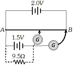
Ans. The internal resistance of a cell, $r=\left(\frac{E-V}{V}\right) R=\frac{R\left(l_{1}-l_{2}\right)}{l_{2}} \quad=\frac{9.5(76.3-64.8)}{64.8} \Omega$ $=\frac{9.5 \times 11.5}{64.8}=1.686 \Omega$
Q. Figure shows a potentiometer circuit for comparison of two resistances. The balance point with a standard resistor $R=10.0 \Omega$ is found to be 58.3 cm, while that with the unknown resistance
X is 68.5 cm. Determine the value of
X. What might you do if you failed to find a balance point with the given cell of
emf E?
[NCERT] 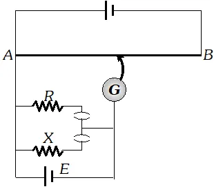
Ans. (i) Let $E_{1}$ and $E_{2}$ be the potential drops across $R$
and $X$ respectively. 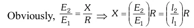 Here, $R=10 \Omega ; l_{1}=58.3 \mathrm{cm}$ and $l_{2}=68.5 \mathrm{cm}$ $\backslash \mathrm{X}=\frac{68.5}{58.3} \times 10=11.75 \Omega$ (ii) We fail to get the balance point with the given cell of emf E, if the potential drop across R or X is greater than the potential difference across the wire AB. In order to obtain the balance point with the given cell E, either the emf of the auxiliary battery (battery connected between the terminals A and B) should be increased or a suitable resistance should be put in series with R and X (so as to decrease the potential drop across the wire AB).
 Q. The four arms of a Wheatstone bridge have the following resistance :
[NCERT] $A B=100 \Omega, B C=10 \Omega, C D=5 \Omega,$ and $D A=60 \Omega$ 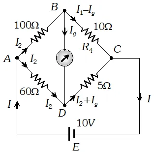 A galvanometer of 15W resistance is connected across BD. Calculate the current through the galvanometer when a potential difference of 10 V is maintained across AC.
 Ans. Considering the mesh BADB, we have $100 I_{1}+15 I_{g}-60 I_{2}=0 \quad \mathrm{P} 20 I_{1}+3 I_{g}-12 I_{2}=0 \quad \ldots(1)$ Considering the mesh BCDB, we have $10\left(I_{1}-I_{S}\right)-15 I_{S}-5\left(I_{2}+I_{S}\right)=0$ $10 I_{1}-30 I_{S}-5 I_{2}=0 \mathrm{P} 2 I_{1}-6 I_{g}-I_{2}=0$ …(ii) Considering the mesh $A D C E A$ 60 $I_{2}+5\left(I_{2}+I_{g}\right)=10$ B $65 I_{2}+5 I_{g}=10 \mathrm{P} 13 I_{2}+I_{g}=2$ …(iii) $\begin{array}{ll}{\text { Multiplying equation (ii) by } 10} \\ {20 I_{1}-60 l_{s}-10 I_{2}=0} & {\ldots \ldots(\mathrm{iv})}\end{array}$ From equations (iv) and (i) we have $63 I_{g}-2 I_{2}=0$ $I_{2}=31.5 I_{g}$ …(v) Substituting the value of into equation (iii), we get $13\left(31.5 I_{g}\right)+I_{g}=2 \mathrm{P} I_{g}=4.87 \mathrm{mA}$
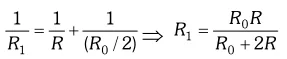
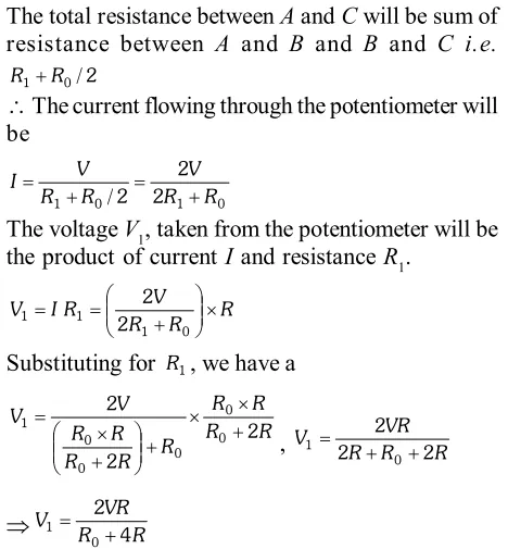
Q. A resistance of
RW draw current from a potentiometer. The potentiometer has a total resistance $R_{0}$ W (figure). A voltage
V is supplied to the potentiometer. Derive an expression for the voltage across
R when the sliding contact is in the middle of the potentiometer.
[NCERT] 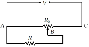
Ans. While the slide is in the middle of the potentiometer only half of its resistance $\left(R_{0} / 2\right)$will be between the points
A and
B. Hence, the total resistance between
A and
B, say
$R_{1}$, will be given by the following expression :
Q. A network of resistors is connected to a 16
V battery with internal resistance of 1W, as shown in figure (a) Compute the equivalent resistance of the network. (b) Obtain the current in each resistor (c) Obtain the voltage drops $V_{A B}, V_{B C}$ and $V_{C D}$
[NCERT] 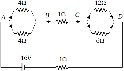
Ans. The network is a simple series and parallel combination of resistors. First the two 4W resistors in parallel are equivalent to a resistor = [(4 × 4)/(4 + 4)] W = 2W In the same way, the 12 W and 6W resistors in parallel are equivalent to a resistor of $[(12 \times 6) /(12+6)] \Omega=4 \Omega$ The equivalent resistance R of the network is obtained by combining these resistors (2W and 4W) with 1W in series, that is $R=2 \Omega+4 \Omega+1 \Omega=7 \Omega$ (b) The total current I in the circuit is $I=\frac{E}{R+r}=\frac{16 \mathrm{V}}{(7+1) \Omega}=2 \mathrm{A}$ Consider the resistors between A and B. If $I_{1}$ is the current in one of the 4 W resistors and $I_{2}$ the current in the other. $I_{1} \times 4=I_{2} \times 4$ that is, $I_{1}=I_{2},$ which is otherwise obvious from the symmetry of the two arms. But $I_{1}+I_{2}=I=2 A .$ Thus, $I_{1}=I_{2}=1 A$ that is, current in each $4 \mathrm{W}$ resistor is $1 \mathrm{A}$. Current in $1 \mathrm{W}$ resistor between $\mathrm{B}$ and $\mathrm{C}$ would be $2 \mathrm{A}$. Now, consider the resistance between $\mathrm{Cand} \mathrm{D} .$ If $I_{3}$ is the current in the $12 \mathrm{W}$ resistor, and $I_{4}$ in the $6 \mathrm{W}$ resistor. $I_{3} \times 12=I_{4} \times 6,$ i.e., $I_{4}=2 I_{3}$ But, $I_{3}+I_{4}=I=2 A$ Thus, $I_{3}=\left(\frac{2}{3}\right) A, I_{4}=\left(\frac{4}{3}\right) A$ that is, the current in the $12 \mathrm{W}$ resistor is $(2 / 3) \mathrm{A},$ while the current in the 6 Wresistor is $(4 / 3) \mathrm{A}$. (c) The voltage drop across $A B$ is $V_{A B}=I_{1} \times 4=1 A \times 4 \Omega=4 \mathrm{V}$. This can also be obtained by multiplying the total current between A and B by the equivalent resistance between A and B, that is $V_{A B}=2 A \times 2 \Omega=4 V$ The voltage drop across $B C$ is $V_{B C}=2 A \times 1 \Omega=2 V$ Finally, the voltage drop across $C D$ is $V_{C D}=12 \Omega \times I_{3}=12 \Omega \times\left(\frac{2}{3}\right) A=8 \mathrm{V}$ This can alternately be obtained by multiplying total current between C and D by the equivalent resistance between C and D, that is $V_{C D}=2 A \times 4 \Omega=8 \mathrm{V}$ Note that the total voltage drop across AD is 4V + 2V +8V = 14 V. Thus, the terminal voltage of the battery is 14 V, while its emf is 16 V. The loss of the voltage (=2 V) is accounted for by the internal resistance 1W of the battery $[2 A \times 1 \Omega=2 \mathrm{V}]$.
Q. A battery of 10 V and negligible internal resistance is connected across the diagonally opposite corners of a cubical network consisting of 12 resistors each of resistance 1 W. Determine the equivalent resistance of the network and the current along each edge of the cube. [NCERT]
Ans. The network is not reducible to a simple series and parallel combinations of resistors. There is however, a clear symmetry in the problem which we can exploit to obtain the equivalent resistance of the network
The paths AA’, AD and AB are obviously symmetrically placed in the network. Thus, the current in each must be the same say, I. Further, at the corners A’, B and D, the incoming current I must split equally into the two outgoing branches. In this manner, the current in all the 12 edges of the cube are easily written down in terms of I, using Kirchhoff’s first rule and the symmetry in the problem. Next take a closed loop, say, ABCC’EA, and apply Kirchhoff’s second rule. $-I R-(1 / 2) I R-I R+E=0$ Where R is the resistance of each edge and E the emf of battery. Thus, $E=\frac{5}{2} I R$ The equivalent resistance $R_{\mathrm{eq}}$ of the network is 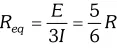 For $R=1 \Omega R_{e q}=(56 / \Omega \text { and for } E=10 \mathrm{V},$ the total current $(=3 \mathrm{I})$ in the network is $3 I=10 \mathrm{V} / 156 \mathrm{R}=12 \mathrm{A},$ i.e. $I=4 \mathrm{A}$ The current flowing in each edge can now be read off from the figure
 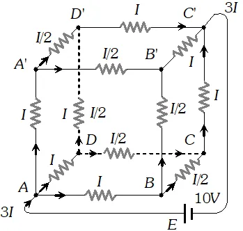 \
\ Q. Figure shows a potentiometer with a cell of 2.0
V and internal resistance $0.40 \Omega$ maintaining a potential drop across the resistor wire
AB. A standard cell which maintains a constant
emf of 1.02
V (for very moderate currents upto a few m
A) gives a balance point at 67.3 cm length of the wire. To ensure very low currents drawn from the standard cell, a very high resistance of $600 \mathrm{k\Omega}$ is put in series with it, which is shorted close to the balance point. The standard cell is then replaced by a cell of unknown
emf E and the balance point found similarly, turns out to be at 82.3 cm length of the wire.
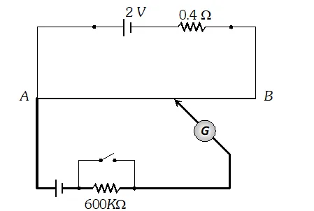 (i) What is the value E ? (ii) What purpose does the high resistance of $600 \mathrm{k\Omega}$ have? (iii) Is the balance point affects by this high resistance ? (iv) Is the balance point affected by the internal resistance of the driver cell ? (v) Would the method work in the above situation if the driver cell of the potentiometer had an emf of 1.0 V instead of 2.0 V ? (vi) Would the circuit work well for determining an extremely small em.f. say of the order of a few mV (such as the typical emf of a thermo-couple) ? If not, how will you modify the circuit ? [NCERT]
 Ans. 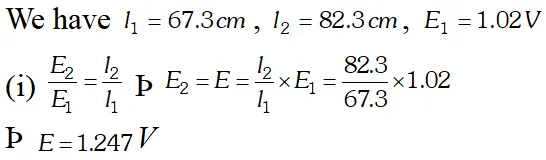 (ii) It is to allow very small current to flow through the galvanometer, then the movable contact is far from the balance point. (iii) No, because there is no flow of current through the standard cell branch. (iv) No, the balance point is not affected. (v) No. If E is greater than emf of the driver cell of the potentiometer, there will be no balance point on the wire AB. (vi) Circuit would not be suitable, because the balance point (for E of the order of a few mV) will be very close to the end A and the percentage error in measurement will be very large. The circuit is modified by putting a suitable resistor R in series with the wire AB so that potential drop across AB is only slightly greater than the emf to be measured. Then the balance point will be at larger length of the wire and the percentage error will be much smaller.
Visit eSaral Website to download or view free study material for JEE & NEET. Also get to know about the strategies to Crack Exam in limited time period.