Alternating Current Class 12 Important Questions Physics

Get important questions of Alternating Current in this question bank for Class 12 Boards exams.View the Physics Question Bank Class 12. These important questions will play significant role in clearing concepts of Physics. This question bank is designed by NCERT keeping in mind and the questions are updated with respect to upcoming Board exams. You will get here all the important questions for class 12 Physics chapter wise CBSE. Learn the concept of alternating current with these important questions of Class 12 point of view. Click Here for Detailed Chapter-wise Notes of PHYSICS for Class 12th, JEE & NEET.
India's Best Exam Preparation for Class 12th - Download Now
Along with the Claa11 and Class 12 important questions of Alternating Current, notes of other Physics chapters are also available at out website.
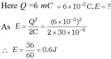 At later times, energy is shared between C and L but total energy remains the same, assuming that there is no loss of energy.
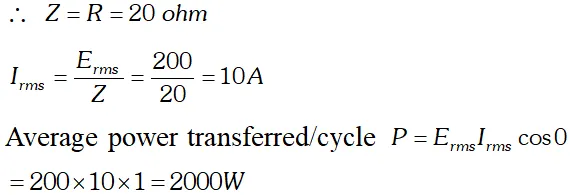
India's Best Exam Preparation for Class 12th - Download Now
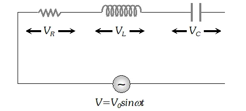 The voltage across resistance R is given by $V_{R}=i R$ it is in phase with current and it is denoted by vector $\overrightarrow{\mathrm{OA}}$ (ii) The voltage across inductor L is given by $V_{L}=i X_{L}$ it leads the current by $90^{\circ}$and it is represented by vector $\overrightarrow{O B}$ along Y (iii) The voltage across capacitor C is given by (iii) The voltage across capacitor C is given by it lag behind the current by 90°, and it is represented by along it lag behind the current by $90^{\circ}$, and it is represented by $\overrightarrow{O C}$ along $Y^{\prime}$
 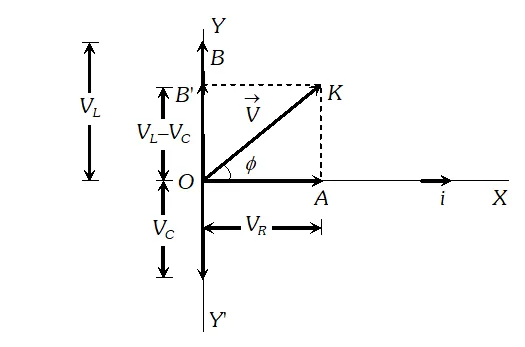 As the voltage across $L$ and $C$ have phase difference by $180^{\circ}$ the voltage across $L C .$ Combination is $\left(V_{L}-V_{c}\right),$ assuming that $V_{L}>V_{C}$ It is represented by vector $O B$ in phasor diagram the resultant of $\frac{1}{O A}$ and $\overline{O B}$ is along $\overline{O K}$ hence from phasor diagram it is clear that $|$
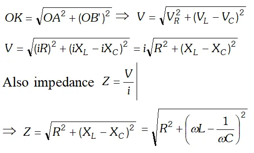
India's Best Exam Preparation for Class 12th - Download Now
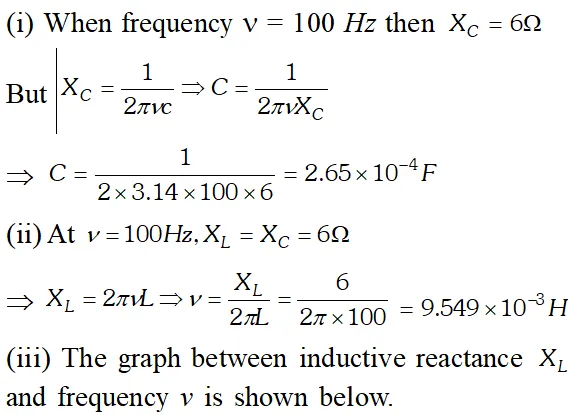
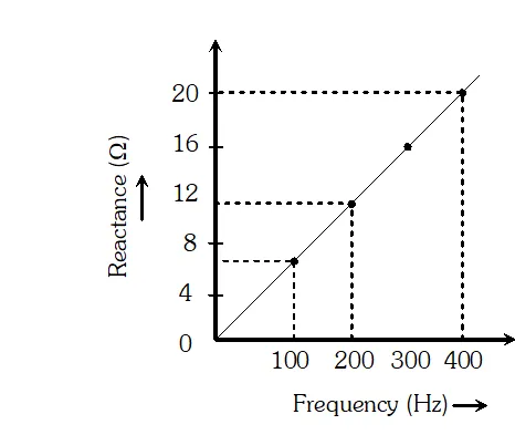
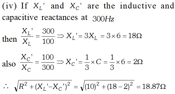
would be the impedance of the combination at 300 Hz. 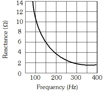
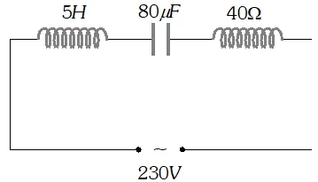 (a) Determine the source frequency which drives the circuit in resonance. (b) Obtain the impedance of the circuit and the amplitude of current at the resonating frequency. (c) Determine the rms potential drops across the three elements of the circuit (d) How do you explain the observation that the algebraic sum of the voltages across the three elements obtained in (c) is greater than the supplied voltage
 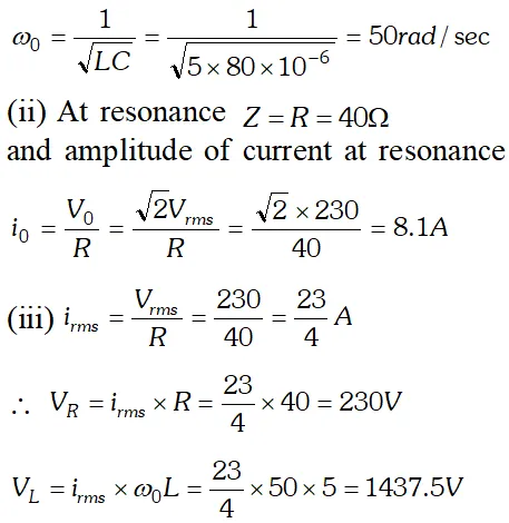 In resonance $V_{C}=V_{L}=1437.5 \mathrm{V}$ The algebraic sum of the three voltages is more than the source voltage of 230 V. These voltages are not in the same phase and cannot be added like ordinary numbers. The voltage across L and C are out of phase and get added to zero. So $\left(V_{R}\right)_{m s}=$ applied rms voltage.
Click Here for Detailed Notes of any chapter.
India's Best Exam Preparation for Class 12th - Download Now
eSaral provides you complete edge to prepare for Board and Competitive Exams like JEE, NEET, BITSAT, etc. We have transformed classroom in such a way that a student can study anytime anywhere. With the help of AI we have made the learning Personalized, adaptive and accessible for each and every one. Visit eSaral Website to download or view free study material for JEE & NEET. Also get to know about the strategies to Crack Exam in limited time period.