Full wave rectifier circuit diagram - Definition, Ripple Factor - eSaral
Table of Contents

A device that rectifies both halves of the ac input is called a full-wave rectifier. If you want to learn about the full-wave rectifier and full-wave rectifier circuit diagram then keep reading.
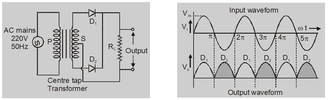
During the first half of the input cycle, the upper end of S coil is at positive potential and the lower end is at the negative potential the junction diode $\mathrm{D}_{1}$ will get forward biased, while the diode $\mathrm{D}_{2}$ reverse biased. The conventional current due to the diode $\mathrm{D}_{1}$ will flow.
When the second half of the input cycle comes, the situation will be exactly reverse. Now, the junction diode $\mathrm{D}_{2}$ will conduct and the current will flow.
$\eta=\frac{\text { dc power delivered to the load }}{\text { ac input power from transformer sec ondary }}$
$=\frac{P_{d c}}{P_{a c}}$
$=\frac{\mathrm{I}^{2} \mathrm{dc} \mathrm{R}_{\mathrm{L}}}{\mathrm{I}_{\mathrm{rms}}^{2}\left(\mathrm{R}_{\mathrm{F}}+\mathrm{R}_{\mathrm{L}}\right)}$
for Full wave rectifier
$\eta=\frac{.812}{1+\frac{R_{\mathrm{F}}}{R_{\mathrm{L}}}}$
if $\frac{R_{F}}{R_{L}}<<1$
$\eta=81.2 \%$
Total Current Output
$\mathrm{I}_{\mathrm{rms}}=\sqrt{\mathrm{I}_{\mathrm{ac}}^{2}+\mathrm{I}^{2} \mathrm{dc}}$
Ripple Factor $=r=\frac{I_{\mathrm{ac}}}{\mathrm{I}_{\mathrm{dc}}}$
$r=\sqrt{\left(\frac{I_{r m s}}{I_{d c}}\right)^{2}-1}$
For full-wave or bridge rectifier
$\mathrm{I}_{\mathrm{rms}}=\frac{\mathrm{I}_{\mathrm{m}}}{\sqrt{2}}$
$I_{\mathrm{dc}}=\frac{2 \mathrm{I}_{\mathrm{m}}}{\pi}$
$r=0.48$
So, that's all from this article. I hope you get the idea about the full-wave rectifier and full-wave rectifier circuit diagram. If you have any confusion related to this blog then feel free to ask in the comments section down below.
Also Read
Half Wave Rectifier Circuit Diagram
To watch Free Learning Videos on physics by Saransh Gupta sir Install the eSaral App.
Full-wave rectifier:
A rectifier that rectifies both halves of the ac input is called a full-wave rectifier.
During the first half of the input cycle, the upper end of S coil is at positive potential and the lower end is at the negative potential the junction diode $\mathrm{D}_{1}$ will get forward biased, while the diode $\mathrm{D}_{2}$ reverse biased. The conventional current due to the diode $\mathrm{D}_{1}$ will flow.
When the second half of the input cycle comes, the situation will be exactly reverse. Now, the junction diode $\mathrm{D}_{2}$ will conduct and the current will flow.
The efficiency of rectifier:
The efficiency rectifier is defined as the ratio of dc output power to the ac input power$\eta=\frac{\text { dc power delivered to the load }}{\text { ac input power from transformer sec ondary }}$
$=\frac{P_{d c}}{P_{a c}}$
$=\frac{\mathrm{I}^{2} \mathrm{dc} \mathrm{R}_{\mathrm{L}}}{\mathrm{I}_{\mathrm{rms}}^{2}\left(\mathrm{R}_{\mathrm{F}}+\mathrm{R}_{\mathrm{L}}\right)}$
for Full wave rectifier
$\eta=\frac{.812}{1+\frac{R_{\mathrm{F}}}{R_{\mathrm{L}}}}$
if $\frac{R_{F}}{R_{L}}<<1$
$\eta=81.2 \%$
Ripple and Ripple factor:
AC components are present in rectifier output these are known as ripple and they are measured in a factor which is known as Ripple FactorTotal Current Output
$\mathrm{I}_{\mathrm{rms}}=\sqrt{\mathrm{I}_{\mathrm{ac}}^{2}+\mathrm{I}^{2} \mathrm{dc}}$
Ripple Factor $=r=\frac{I_{\mathrm{ac}}}{\mathrm{I}_{\mathrm{dc}}}$
$r=\sqrt{\left(\frac{I_{r m s}}{I_{d c}}\right)^{2}-1}$
For full-wave or bridge rectifier
$\mathrm{I}_{\mathrm{rms}}=\frac{\mathrm{I}_{\mathrm{m}}}{\sqrt{2}}$
$I_{\mathrm{dc}}=\frac{2 \mathrm{I}_{\mathrm{m}}}{\pi}$
$r=0.48$
So, that's all from this article. I hope you get the idea about the full-wave rectifier and full-wave rectifier circuit diagram. If you have any confusion related to this blog then feel free to ask in the comments section down below.
Also Read
Half Wave Rectifier Circuit Diagram
To watch Free Learning Videos on physics by Saransh Gupta sir Install the eSaral App.