Half wave rectifier circuit diagram - Definition, Explanation - eSaral
Table of Contents

A device that converts alternating current into Direct current is called a rectifier. If you want to learn about the half-wave rectifier and half-wave rectifier circuit diagram then you are at the right place.
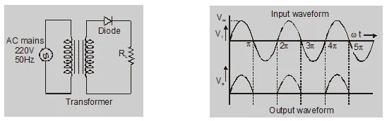
During the first half of the input cycle, the junction diode gets forward bias. The conventional current will flow. The upper end of $R_{L}$ will be positive potential with respect to the lower end during the second half cycle junction diode will get reverse biased and hence no output will be obtained across $R_{L}$.
Input voltage
$\mathrm{V}_{\mathrm{i}}=\mathrm{V}_{\mathrm{m}} \sin \omega \mathrm{t}$
$\mathrm{i}=\mathrm{I}_{\mathrm{m}} \sin \omega \mathrm{t}$
for $0 \leq \omega t \leq \pi$
$\mathrm{i}=0$
for $\pi<\omega t<2 \pi$
$I_{m}=\frac{V_{m}}{R_{f}+R_{L}}$
here $\mathrm{R}_{\mathrm{f}}=$ forward resistance of diode
$R_{L}$ = load resistance
a. dc output current :
$\mathrm{I}_{\mathrm{dc}}=\frac{1}{2 \pi} \int_{0}^{2 \pi} \mathrm{idt}$
$=\frac{1}{2 \pi}\left[\int_{0}^{\pi} \mathrm{I}_{\mathrm{m}} \sin t \mathrm{dt}+\int_{\pi}^{2 \pi} 0 \mathrm{dt}\right]$
$\mathrm{I}_{\mathrm{dc}}=\frac{\mathrm{I}_{\mathrm{m}}}{\pi}=0.318 \mathrm{I}_{\mathrm{m}}$
b. dc output voltage:
$V_{d c}=I_{d c} \times R_{L}$
$=\frac{I_{m}}{\pi} \times R_{L}$
$=\frac{\mathrm{V}_{\mathrm{m}}}{\pi\left[1+\left(\mathrm{R}_{\mathrm{f}} / \mathrm{R}_{\mathrm{L}}\right)\right]}$
$V_{d c}=\frac{V_{m}}{\pi}=0.318 \mathrm{~V}_{\mathrm{m}}$
c. (Root mean square) RMS current:
$I_{r m s}=\left[\frac{1}{2 \pi} \int_{0}^{2 \pi} i^{2} d(t)\right]^{1 / 2}$
$=\frac{I_{m}}{2}$
same
$V_{r m s}=\frac{V_{m}}{2}$
So, that's all from this blog. I hope you enjoyed this explanation of the half-wave rectifier and half-wave rectifier circuit diagram. If you liked this article then please share it with your friends.
Also Read
What is Diode in electronics
To watch Free Learning Videos on physics by Saransh Gupta sir Install the eSaral App.
Application of diode as a rectifier:
An electronic device that converts alternating current into Direct current is called a rectifier.Half wave rectifier:
A rectifier, which rectifies only one half of each ac supply cycle is called a half-wave rectifier.
During the first half of the input cycle, the junction diode gets forward bias. The conventional current will flow. The upper end of $R_{L}$ will be positive potential with respect to the lower end during the second half cycle junction diode will get reverse biased and hence no output will be obtained across $R_{L}$.
Input voltage
$\mathrm{V}_{\mathrm{i}}=\mathrm{V}_{\mathrm{m}} \sin \omega \mathrm{t}$
$\mathrm{i}=\mathrm{I}_{\mathrm{m}} \sin \omega \mathrm{t}$
for $0 \leq \omega t \leq \pi$
$\mathrm{i}=0$
for $\pi<\omega t<2 \pi$
$I_{m}=\frac{V_{m}}{R_{f}+R_{L}}$
here $\mathrm{R}_{\mathrm{f}}=$ forward resistance of diode
$R_{L}$ = load resistance
a. dc output current :
$\mathrm{I}_{\mathrm{dc}}=\frac{1}{2 \pi} \int_{0}^{2 \pi} \mathrm{idt}$
$=\frac{1}{2 \pi}\left[\int_{0}^{\pi} \mathrm{I}_{\mathrm{m}} \sin t \mathrm{dt}+\int_{\pi}^{2 \pi} 0 \mathrm{dt}\right]$
$\mathrm{I}_{\mathrm{dc}}=\frac{\mathrm{I}_{\mathrm{m}}}{\pi}=0.318 \mathrm{I}_{\mathrm{m}}$
b. dc output voltage:
$V_{d c}=I_{d c} \times R_{L}$
$=\frac{I_{m}}{\pi} \times R_{L}$
$=\frac{\mathrm{V}_{\mathrm{m}}}{\pi\left[1+\left(\mathrm{R}_{\mathrm{f}} / \mathrm{R}_{\mathrm{L}}\right)\right]}$
$V_{d c}=\frac{V_{m}}{\pi}=0.318 \mathrm{~V}_{\mathrm{m}}$
c. (Root mean square) RMS current:
$I_{r m s}=\left[\frac{1}{2 \pi} \int_{0}^{2 \pi} i^{2} d(t)\right]^{1 / 2}$
$=\frac{I_{m}}{2}$
same
$V_{r m s}=\frac{V_{m}}{2}$
So, that's all from this blog. I hope you enjoyed this explanation of the half-wave rectifier and half-wave rectifier circuit diagram. If you liked this article then please share it with your friends.
Also Read
What is Diode in electronics
To watch Free Learning Videos on physics by Saransh Gupta sir Install the eSaral App.