Kelvin Bridge - Definition and Diagram || Current Electricity Class 12, JEE & NEET

The Kelvin bridge or Thompson bridge is used for measuring the unknown resistances having a value less than 1Ω. It is the modified form of the Wheatstone Bridge. Here we will study about Kelvin Bridge, its Diagram and the equation of Kelvin Bridge.
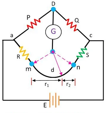 The r is the resistance of the contacts that connect the unknown resistance R to the standard resistance S. The ‘m’ and ‘n’ show the range between which the galvanometer is connected for obtaining a point.
When the galvanometer is connected to point ‘m’, the lead resistance r is added to the standard resistance S. Thereby the very low indication obtains for unknown resistance R. And if the galvanometer is connected to point n then the r adds to the R, and hence the high value of unknown resistance is obtained. Thus, at point n and m either very high or very low value of unknown resistance is obtained.
So, instead of connecting the galvanometer from point, m and n we chose any intermediate point say d where the resistance of lead r is divided into two equal parts, i.e., r1 and r2
$\frac{r_{1}}{r_{2}}=\frac{P}{Q} \ldots \ldots$ equ ( 1)
The presence of $\mathrm{r}_{1}$ causes no error in the measurement of unknown resistance.
$$
R+r_{1}=\frac{P}{Q} \cdot\left(S+r_{2}\right)
$$
From equation $(1),$ we get
$$
\begin{aligned}
\frac{r_{1}}{r_{1}+r_{2}} &=\frac{P}{P+Q} \\
r_{1}=& \frac{P}{P+Q} \cdot r
\end{aligned}
$$
$a S$
$$
\begin{aligned}
r_{1}+r_{2} &=r \\
r_{2}=& \frac{Q}{P+Q} \cdot r \\
R+\frac{P}{P+Q} \cdot r &=\frac{P}{Q}\left(S+\frac{Q}{P+Q} r\right) \\
R &=\frac{P}{Q} \cdot S
\end{aligned}
$$
The above equation shows that if the galvanometer connects at point d then the resistance of lead will not affect their results.
The above mention process is practically not possible to implement. For obtaining the desired result, the actual resistance of exact ratio connects between the point m and n and the galvanometer connects at the junction of the resistor.
The r is the resistance of the contacts that connect the unknown resistance R to the standard resistance S. The ‘m’ and ‘n’ show the range between which the galvanometer is connected for obtaining a point.
When the galvanometer is connected to point ‘m’, the lead resistance r is added to the standard resistance S. Thereby the very low indication obtains for unknown resistance R. And if the galvanometer is connected to point n then the r adds to the R, and hence the high value of unknown resistance is obtained. Thus, at point n and m either very high or very low value of unknown resistance is obtained.
So, instead of connecting the galvanometer from point, m and n we chose any intermediate point say d where the resistance of lead r is divided into two equal parts, i.e., r1 and r2
$\frac{r_{1}}{r_{2}}=\frac{P}{Q} \ldots \ldots$ equ ( 1)
The presence of $\mathrm{r}_{1}$ causes no error in the measurement of unknown resistance.
$$
R+r_{1}=\frac{P}{Q} \cdot\left(S+r_{2}\right)
$$
From equation $(1),$ we get
$$
\begin{aligned}
\frac{r_{1}}{r_{1}+r_{2}} &=\frac{P}{P+Q} \\
r_{1}=& \frac{P}{P+Q} \cdot r
\end{aligned}
$$
$a S$
$$
\begin{aligned}
r_{1}+r_{2} &=r \\
r_{2}=& \frac{Q}{P+Q} \cdot r \\
R+\frac{P}{P+Q} \cdot r &=\frac{P}{Q}\left(S+\frac{Q}{P+Q} r\right) \\
R &=\frac{P}{Q} \cdot S
\end{aligned}
$$
The above equation shows that if the galvanometer connects at point d then the resistance of lead will not affect their results.
The above mention process is practically not possible to implement. For obtaining the desired result, the actual resistance of exact ratio connects between the point m and n and the galvanometer connects at the junction of the resistor.
 The galvanometer is connected between the arms p and q at a point d. The point d places at the centre of the resistance r between the point m and n for removing the effect of the connecting lead resistance which is placed between the unknown resistance R and standard resistance S.
The ratio of p/q is made equal to the P/Q. Under balance condition zero current flows through the galvanometer. The potential difference between Point $a$ and $b$ is equivalent to the voltage drop between the points $E_{\mathrm{amd}}$.
Now,
$$
\begin{array}{c}
{E_{a b}=\frac{P}{P+Q} E_{a c}} \\
{E_{a c}=I\left[R+S+\frac{(p+q) r}{p+q+r}\right] \ldots \ldots \text { equ }(1)} \\
{E_{a m d}=I\left[R+\frac{p}{(p+q)}\left\{\frac{(p+q) r}{p+q+r}\right\}\right]} \\
{E_{a c}=I\left[\frac{p r}{p+q+r}\right] \ldots \ldots \ldots e q u(2)}
\end{array}
$$
For zero galvanometer deflection,
$$
\begin{array}{c}
{E_{a c}=E_{a m d}} \\
{\frac{P}{P+Q} \cdot I\left[R+\frac{p}{(p+q)}\left\{\frac{(p+q) r}{p+q+r}\right\}\right]=I\left[\frac{p r}{p+q+r}\right]} \\
{R=\frac{P}{Q} \cdot S+\frac{p r}{p+q+r}\left[\frac{P}{Q}-\frac{p}{q}\right]}
\end{array}
$$
As we known, $\mathbf{P} / \mathbf{Q}=\mathbf{p} / \mathbf{q}$ then above equation becomes
$$
R=\frac{P}{Q} \cdot S
$$
The above equation is the working equations of the Kelvins bridge. The equation shows that the result obtains from the Kelvin double bridge is free from the impact of the connecting lead resistance.
For obtaining the appropriate result, it is very essentials that the ratio of their arms is equal. The unequal arm ratio causes the error in the result. Also, the value of resistance r should be kept minimum for obtaining the exact result.
The thermo-electric EMF induces in the bridge during the reading. This effect can be reduced by measuring the resistance with the reverse battery connection. The real value of the resistance obtains by takings the means of the two.
Also Read:
Combination of Resistances
Download eSaral APP
The galvanometer is connected between the arms p and q at a point d. The point d places at the centre of the resistance r between the point m and n for removing the effect of the connecting lead resistance which is placed between the unknown resistance R and standard resistance S.
The ratio of p/q is made equal to the P/Q. Under balance condition zero current flows through the galvanometer. The potential difference between Point $a$ and $b$ is equivalent to the voltage drop between the points $E_{\mathrm{amd}}$.
Now,
$$
\begin{array}{c}
{E_{a b}=\frac{P}{P+Q} E_{a c}} \\
{E_{a c}=I\left[R+S+\frac{(p+q) r}{p+q+r}\right] \ldots \ldots \text { equ }(1)} \\
{E_{a m d}=I\left[R+\frac{p}{(p+q)}\left\{\frac{(p+q) r}{p+q+r}\right\}\right]} \\
{E_{a c}=I\left[\frac{p r}{p+q+r}\right] \ldots \ldots \ldots e q u(2)}
\end{array}
$$
For zero galvanometer deflection,
$$
\begin{array}{c}
{E_{a c}=E_{a m d}} \\
{\frac{P}{P+Q} \cdot I\left[R+\frac{p}{(p+q)}\left\{\frac{(p+q) r}{p+q+r}\right\}\right]=I\left[\frac{p r}{p+q+r}\right]} \\
{R=\frac{P}{Q} \cdot S+\frac{p r}{p+q+r}\left[\frac{P}{Q}-\frac{p}{q}\right]}
\end{array}
$$
As we known, $\mathbf{P} / \mathbf{Q}=\mathbf{p} / \mathbf{q}$ then above equation becomes
$$
R=\frac{P}{Q} \cdot S
$$
The above equation is the working equations of the Kelvins bridge. The equation shows that the result obtains from the Kelvin double bridge is free from the impact of the connecting lead resistance.
For obtaining the appropriate result, it is very essentials that the ratio of their arms is equal. The unequal arm ratio causes the error in the result. Also, the value of resistance r should be kept minimum for obtaining the exact result.
The thermo-electric EMF induces in the bridge during the reading. This effect can be reduced by measuring the resistance with the reverse battery connection. The real value of the resistance obtains by takings the means of the two.
Also Read:
Combination of Resistances
Download eSaral APP
Why there is a requirement of Kelvin Bridge?
Wheatstone bridge use for measuring the resistance from a few ohms to several kilo-ohms. But error occurs in the result when it is used for measuring the low resistance. This is the reason because of which the Wheatstone Bridge is modified, and the Kelvin bridge obtains. The Kelvin bridge is suitable for measuring the low resistance.Modification of Wheatstone Bridge
In Wheatstone Bridge, while measuring the low-value resistance, the resistance of their lead and contacts increases the resistance of their total measured value. This can easily be understood with the help of the circuit diagram.
The r is the resistance of the contacts that connect the unknown resistance R to the standard resistance S. The ‘m’ and ‘n’ show the range between which the galvanometer is connected for obtaining a point.
When the galvanometer is connected to point ‘m’, the lead resistance r is added to the standard resistance S. Thereby the very low indication obtains for unknown resistance R. And if the galvanometer is connected to point n then the r adds to the R, and hence the high value of unknown resistance is obtained. Thus, at point n and m either very high or very low value of unknown resistance is obtained.
So, instead of connecting the galvanometer from point, m and n we chose any intermediate point say d where the resistance of lead r is divided into two equal parts, i.e., r1 and r2
$\frac{r_{1}}{r_{2}}=\frac{P}{Q} \ldots \ldots$ equ ( 1)
The presence of $\mathrm{r}_{1}$ causes no error in the measurement of unknown resistance.
$$
R+r_{1}=\frac{P}{Q} \cdot\left(S+r_{2}\right)
$$
From equation $(1),$ we get
$$
\begin{aligned}
\frac{r_{1}}{r_{1}+r_{2}} &=\frac{P}{P+Q} \\
r_{1}=& \frac{P}{P+Q} \cdot r
\end{aligned}
$$
$a S$
$$
\begin{aligned}
r_{1}+r_{2} &=r \\
r_{2}=& \frac{Q}{P+Q} \cdot r \\
R+\frac{P}{P+Q} \cdot r &=\frac{P}{Q}\left(S+\frac{Q}{P+Q} r\right) \\
R &=\frac{P}{Q} \cdot S
\end{aligned}
$$
The above equation shows that if the galvanometer connects at point d then the resistance of lead will not affect their results.
The above mention process is practically not possible to implement. For obtaining the desired result, the actual resistance of exact ratio connects between the point m and n and the galvanometer connects at the junction of the resistor.
Kelvin Double Circuit Bridge
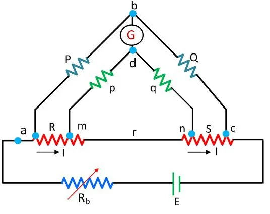
The ratio of the arms p and q are used to connect the galvanometer at the right place between the point j and k. The j and k reduce the effect of connecting lead. The P and Q is the first ratio of the arm and p and q is the second arm ratio.
The galvanometer is connected between the arms p and q at a point d. The point d places at the centre of the resistance r between the point m and n for removing the effect of the connecting lead resistance which is placed between the unknown resistance R and standard resistance S.
The ratio of p/q is made equal to the P/Q. Under balance condition zero current flows through the galvanometer. The potential difference between Point $a$ and $b$ is equivalent to the voltage drop between the points $E_{\mathrm{amd}}$.
Now,
$$
\begin{array}{c}
{E_{a b}=\frac{P}{P+Q} E_{a c}} \\
{E_{a c}=I\left[R+S+\frac{(p+q) r}{p+q+r}\right] \ldots \ldots \text { equ }(1)} \\
{E_{a m d}=I\left[R+\frac{p}{(p+q)}\left\{\frac{(p+q) r}{p+q+r}\right\}\right]} \\
{E_{a c}=I\left[\frac{p r}{p+q+r}\right] \ldots \ldots \ldots e q u(2)}
\end{array}
$$
For zero galvanometer deflection,
$$
\begin{array}{c}
{E_{a c}=E_{a m d}} \\
{\frac{P}{P+Q} \cdot I\left[R+\frac{p}{(p+q)}\left\{\frac{(p+q) r}{p+q+r}\right\}\right]=I\left[\frac{p r}{p+q+r}\right]} \\
{R=\frac{P}{Q} \cdot S+\frac{p r}{p+q+r}\left[\frac{P}{Q}-\frac{p}{q}\right]}
\end{array}
$$
As we known, $\mathbf{P} / \mathbf{Q}=\mathbf{p} / \mathbf{q}$ then above equation becomes
$$
R=\frac{P}{Q} \cdot S
$$
The above equation is the working equations of the Kelvins bridge. The equation shows that the result obtains from the Kelvin double bridge is free from the impact of the connecting lead resistance.
For obtaining the appropriate result, it is very essentials that the ratio of their arms is equal. The unequal arm ratio causes the error in the result. Also, the value of resistance r should be kept minimum for obtaining the exact result.
The thermo-electric EMF induces in the bridge during the reading. This effect can be reduced by measuring the resistance with the reverse battery connection. The real value of the resistance obtains by takings the means of the two.
Also Read:
Combination of Resistances
Download eSaral APP