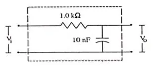
Figure shows a typical circuit for low pass filter.

Question:
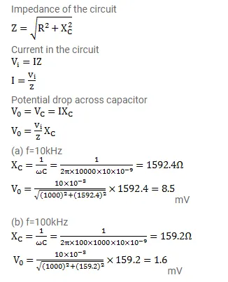
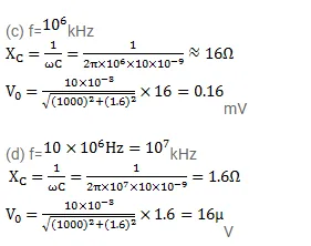
Figure shows a typical circuit for low pass filter. An AC input $\mathrm{v}_{\mathrm{i}}=10 \mathrm{mV}$ is applied at the left end and the output $\mathrm{v}_{0}$ is received at the right end. Find the output voltages for $\mathrm{v}=10 \mathrm{kHz}, 100 \mathrm{kHz}, 1.0 \mathrm{MHz}$ and $10.0 \mathrm{MHz}$. Note that as the frequency is increased the output decreases and hence the name low pass filter.
Solution: