Ampere's Circuital Law and it Applications || Magnetic Effects of Current Class 12
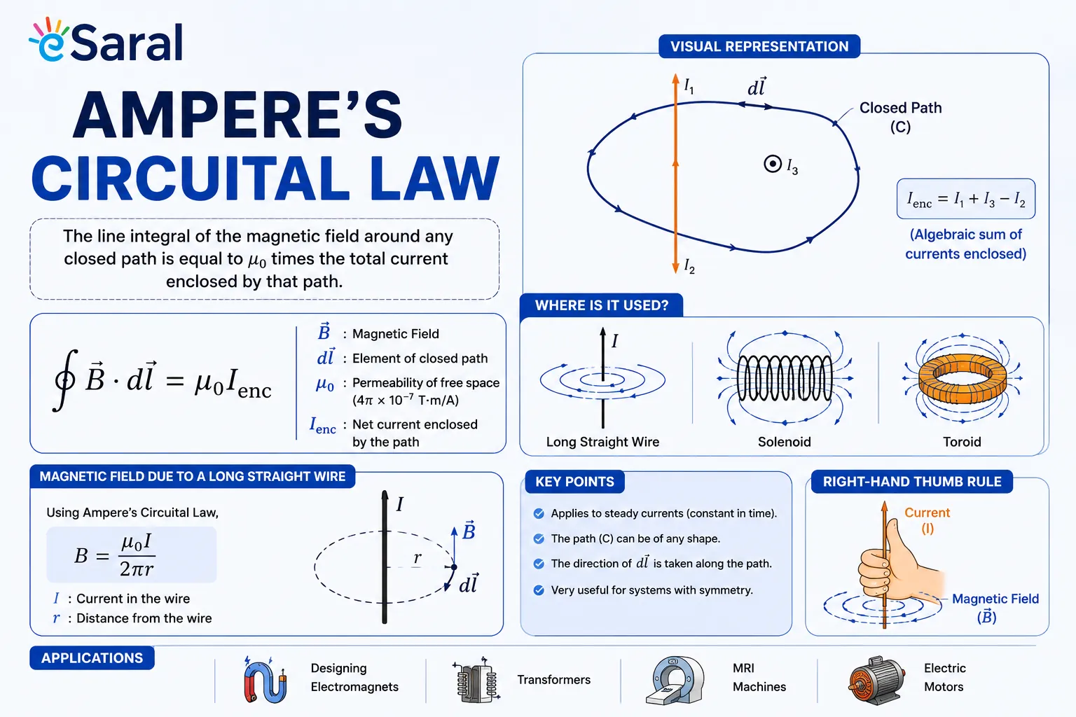
Table of Contents

eSaral › Class 12 Physics Notes › Applications of Ampere's Law in Physics

Do you know about Ampere's Circuital Law? Well, it is a current distribution that helps us to calculate the magnetic field, and yes, Biot-Savart's law does the same, but Ampere’s law uses the case of high symmetry. We will first understand Ampere’s circuital law, its definition, formulae, & Applications of Ampere's Law in detail.
- Magnetic induction due to a long current-carrying wire.
- The Magnetic field created by a long current-carrying conducting cylinder
- Magnetic field due to a conducting current-carrying hollow cylinder
Ampere's Circuital Law
Ampere's circuital law states that the line integral of magnetic field induction $\overrightarrow{\mathrm{B}}$ around any closed path in a vacuum is equal to $\mu_{0}$ times the total current threading the closed path, i.e., 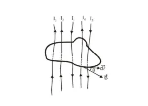
![]()
This result is independent of the size and shape of the closed curve enclosing a current.
This is known as Ampere's circuital law.
Ampere's law gives another method to calculate the magnetic field due to a given current distribution.
Ampere's law may be derived from the Biot-Savart law, and the Biot-Savart law may be derived from Ampere's law.
Ampere's law is more useful under certain symmetrical conditions.
Biot-Savart law is based on experimental results, whereas Ampere's law is based on mathematical.
Applications of Ampere's Law
(a) Magnetic induction due to a long current-carrying wire.
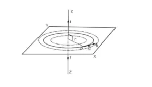
Consider a long straight conductor Z-Z' along the z-axis. Let I be the current flowing in the direction as shown in Fig. The magnetic field is produced around the conductor. The magnetic lines of force are concentric circles in the XY plane, as shown by dotted lines. Let the magnitude of the magnetic field induction produced at a point P at a distance r from the conductor be
Consider a closed circular loop as shown in the figure.
 According to Ampere's law $\oint \overrightarrow{\mathrm{B}} . \overrightarrow{\mathrm{d}} \ell=\mu_{0} \sum \mathrm{I}$
The direction of $\overrightarrow{\mathrm{B}}$ at every point is along the tangent to the circle.
Consider a small element $\overrightarrow{\mathrm{d} \ell}$ of the circle of radius r at P. The direction of $\overrightarrow{\mathrm{B}}$ and $\overrightarrow{\mathrm{d} \ell}$ the same. Therefore, angle between them is zero.
Line integral of $\overrightarrow{\mathrm{B}}$ around the complete circular path of radius $\mathrm{r}$ is given by  $\oint \overrightarrow{\mathrm{B}} \cdot \overrightarrow{\mathrm{d}} \ell=\oint \mathrm{B} \mathrm{d} \ell \cos 0^{\circ}$ $=\quad \mathrm{B} \oint \mathrm{d} \ell=\mathrm{B} \times 2 \pi \mathrm{r}$ $(\oint \mathrm{d} \ell=2 \pi \mathrm{r}=$ cicumference of the circle.) and $\quad \sum I=I$
So we get $\mathrm{B} \times 2 \pi \mathrm{r}=\mu_{0} \mathrm{I}$ 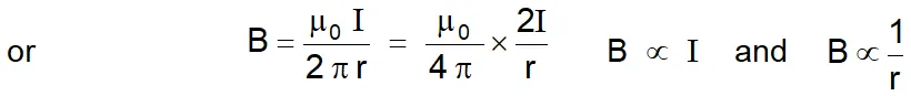
(b) Magnetic field created by a long current-carrying conducting cylinder
A long straight wire of radius R carries a steady current I that is uniformly distributed through the cross-section of the wire.
To find the behavior of the magnetic field due to this wire, let us divide the whole region into two parts.
(a) $\mathrm{r} \geq \mathrm{R}$ and
(b) $\mathrm{r}<\mathrm{R}$
$r=$ distance from the centre of the wire.
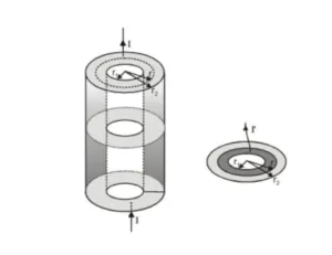
For $\mathrm{r} \geq \mathrm{R}:$ For closed circular path denoted by ( 1) from symmetry, $\overrightarrow{\mathrm{B}}$ must be constant in magnitude and parallel to $\overrightarrow{\mathrm{d} \ell}$ at every point on this circle. Because the total current passing through the plane of the circle is I.


For $\mathrm{r}<\mathrm{R}:$ The current $\mathrm{I}$ passing through the plane of circle 2 is less than the total current I. Because the current is uniform over the cross-section of the wire.
Current through unit area $=\frac{\mathrm{I}}{\pi \mathrm{R}^{2}}$
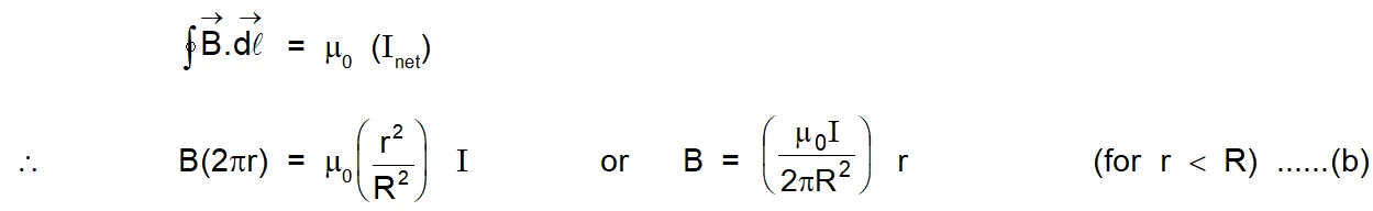
So current through area enclosed by circle 2 is $\mathrm{I}^{\prime}=\frac{\mathrm{I} \pi \mathrm{r}^{2}}{\pi \mathrm{R}^{2}}$ 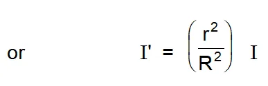
Now we apply Ampere's law for circle $2 .$ 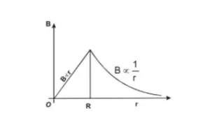
 The magnitude of the magnetic field versus $r$ for this configuration is plotted in figure. Note that inside the wire $\mathrm{B} \rightarrow 0$ as $\mathrm{r} \rightarrow 0 .$ Note also that eqn. (a) and eqn (b) give the same value of the magnetic field at $r=R,$ demonstrating that the magnetic field is continuous at the surface of the wire.
(c) Magnetic field due to a conducting current carrying hollow cylinder
Consider a conducting hollow cylinder with inner radius $r_{1}$ and outer radius $r_{2} .$ And current $\mathrm{I}$ is flowing through it.
 (I) $\quad$ For $r
$\sum \mathrm{I}=0$ and hence $\quad B=0$
(II) $\quad$ For $r_{1}
Now current I is flowing through area $\left[\pi r_{2}^{2}-\pi r_{1}^{2}\right]$
So, current per unit area $=\frac{I}{\pi\left(r_{2}^{2}-r_{1}^{2}\right)}$
$\therefore$ current flowing through area in bet" $\mathrm{r}_{1}<\mathrm{r}<\mathrm{r}_{2}$ is $\mathrm{I}=\frac{\mathrm{I}}{\pi\left(\mathrm{r}_{2}^{2}-\mathrm{r}_{1}^{2}\right)} \times\left(\pi \mathrm{r}^{2}-\pi \mathrm{r}_{1}^{2}\right)$
by using ampere's law for circle of radius $\mathrm{r} \oint \overrightarrow{\mathrm{B}} . \overrightarrow{\mathrm{d}} \vec{\ell}=\mu_{0} \sum \mathrm{I}$
or $\quad \oint B d \ell \cos 0^{\circ}=\mu_{0}\left[\frac{I\left(r^{2}-r_{1}^{2}\right)}{r_{2}^{2}-r_{1}^{2}}\right]$
or $\quad \mathrm{B} \oint \mathrm{d} \ell=\mu_{0} \mathrm{I}\left[\frac{\mathrm{r}^{2}-\mathrm{r}_{1}^{2}}{\mathrm{r}_{2}^{2}-\mathrm{r}_{1}^{2}}\right]$
or $\quad B=\frac{\mu_{0} I}{2 \pi r}\left[\frac{r^{2}-r_{1}^{2}}{r_{1}^{2}-r_{1}^{2}}\right]$
$[\because \oint \mathrm{d} \ell=2 \pi \mathrm{r}]$

(a) For $r=r_{2}$
$B=\frac{\mu_{0} I}{2 \pi r_{2}}$
(b) For $r>r_{2}$
$B=\frac{\mu_{0} I}{2 \pi r}$
Also Read: Biot Savart's Law Click here for the Video tutorials of Magnetic Effect of Current Class 12
About eSaral At eSaral we are offering a complete platform for IIT-JEE & NEET preparation. The main mission behind eSaral is to provide education to each and every student in India by eliminating the Geographic and Economic factors, as a nation’s progress and development depends on the availability of quality education to each and every one. With the blend of education & technology, eSaral team made the learning personalized & adaptive for everyone.
For free video lectures and complete study material, Download eSaral APP.
Frequently Asked Questions
Find answers to common questions.
What is the difference between Ampere's law and Biot-Savart law?
Both laws calculate the magnetic field due to a current. Biot-Savart law works for any geometry but requires complex vector integration. Ampere's law is simpler but only practical when the current distribution has high symmetry (cylindrical or planar), allowing B to be pulled out of the integral. For a long straight wire, both give B = μ₀I/(2πr)
What is the formula for Ampere's Circuital Law?
The formula is ∮ B · dℓ = μ₀ΣI, where B is the magnetic field, dℓ is the infinitesimal path element along the closed Amperian loop, μ₀ = 4π × 10⁻⁷ T·m/A is the permeability of free space, and ΣI is the algebraic sum of all currents enclosed by the loop.
What does Ampere's Circuital Law state in simple words?
Ampere's Circuital Law says that if you walk along any closed loop in a magnetic field and add up (integrate) B · dℓ at every step, the total equals μ₀ multiplied by the net current passing through the area inside the loop. It is a way to link the magnetic field around a closed path to the current that creates it.
Is Ampere's law in the JEE Main and JEE Advanced syllabus?
Yes. Ampere's Circuital Law is explicitly listed in the JEE Main and JEE Advanced syllabus under Magnetic Effects of Current and Magnetism. Questions typically test the statement, the choice of Amperian loop, derivations for straight wire and cylindrical conductors, and B-vs-r graph interpretation. It is also a full chapter in CBSE Class 12 Physics (Chapter 4).
How does the magnetic field vary inside a solid cylindrical conductor?
Inside a solid cylinder of radius R carrying uniform current I, the enclosed current for a loop of radius r < R is I' = Ir²/R². Applying Ampere's law gives B = μ₀Ir/(2πR²). The field increases linearly with r, reaching its maximum value B = μ₀I/(2πR) at the surface, and then decreasing as 1/r outside
Why is the magnetic field zero inside a hollow cylindrical conductor?
Inside the hollow cavity (r < r₁), any Amperian loop encloses zero current. Since ∮ B · dℓ = μ₀ × 0 = 0 and by symmetry B must be constant on the loop, the only consistent value is B = 0. Current flowing in the walls of the cylinder has no enclosed contribution to a loop drawn entirely inside the cavity