NCERT Solutions for Class 12 Physics Chapter 3 Current Electricity PDF - eSaral


NCERT Solutions for Class 12 Physics Chapter 3 Current Electricity PDF
Hey, are you a class 12 student and looking for ways to download NCERT Solutions for Class 12 Physics Chapter 3 Current Electricity PDF? If yes. Then read this post till the end.In this article, we have listed NCERT Solutions for Class 12 Physics Chapter 3 Current Electricity in PDF that are prepared by Kota’s top IITian Faculties by keeping Simplicity in mind.
If you want to learn and understand class 12 Physics Chapter 3 "Current Electricity" in an easy way then you can use these solutions PDF.
NCERT Solutions helps students to Practice important concepts of subjects easily. Class 12 Physics solutions provide detailed explanations of all the NCERT questions that students can use to clear their doubts instantly.
If you want to score high in your class 12 Physics Exam then it is very important for you to have a good knowledge of all the important topics, so to learn and practice those topics you can use eSaral NCERT Solutions.
In this article, we have listed NCERT Solutions for Class 12 Physics Chapter 3 Current Electricity PDF that you can download to start your preparations anytime.
So, without wasting more time Let’s start.
Download NCERT Solutions for Class 12 Physics Chapter 3 Current Electricity PDF
Question 1. The storage battery of a car has an emf of $12 \mathrm{~V}$. If the internal resistance of the battery is $0.4 \Omega$, what is the maximum current that can be drawn from the battery?
Solution. Given:
emf of the battery $(E)=12 \mathrm{~V}$
Internal resistance of the battery $(r)=0.4 \Omega$
Let the maximum current drawn from the battery is I
By Ohm's law,
$E=I r$
$I=\frac{E}{r}$
$I=\frac{12}{0.4}=30 \mathrm{~A}$
$\therefore 30 \mathrm{~A}$ is the maximum current drawn from the battery.
Question 2. A battery of emf $10 \mathrm{~V}$ and internal resistance $3 \Omega$ is connected to a resistor. If the current in the circuit is $0.5 \mathrm{~A}$, what is the resistance of the resistor? What is the terminal voltage of the battery when the circuit is closed?
Solution. Given:
emf of the battery, $E$, is $10 \mathrm{~V}$
Internal resistance of the battery, $r,=3 \Omega$,
Current in the circuit, $I,=0.5 \mathrm{~A}$,
Resistance of the resistor is $R$.
According to Ohm's law,
$I=\frac{E}{R+r}$
$\Rightarrow R+r=\frac{E}{I}$
$=\frac{10}{0.5}=20 \Omega$
$\therefore R=20-3=17 \Omega$
The terminal voltage of the resistor $=V$
According to Ohm's law,
$V=I R$
$=0.5 \times 17$
$=8.5 \mathrm{~V}$
$\therefore$ The terminal voltage is $8.5, V$ and the resistance of the resistor is $17 \Omega$.
Question 3. (a) Three resistors $1 \Omega, 2 \Omega$, and $3 \Omega$, are combined in series. What is the total resistance of the combination?
(b) If the combination is connected to a battery of emf $12 \mathrm{~V}$ and negligible internal resistance, obtain the potential drop across each resistor.
Solution. (a) The resistors $1 \Omega, 2 \Omega$, and $3 \Omega$ are combined in series.
Hence, total resistance $=1+2+3=6 \Omega$
(b) Current flowing through the circuit $=I$
Emf of the battery, $E$ is $12 \mathrm{~V}$
The total resistance of the circuit in series combination, $R$ is $6 \Omega$
According to Ohm's law
$I=\frac{E}{R}$
$=\frac{12}{6}=2 \mathrm{~A}$
Let the potential drop across $1 \Omega$ resistor is $V_{1}$
The value of $V_{1}$ obtained by Ohm's law is:
$V_{1}=2 \times 1=2 \mathrm{~V} \ldots(i)$
Let the potential drop across $2 \Omega$ resistor is $V_{2}$
Again, from Ohm's law, the value of $V_{2}$ can be obtained as
$V_{2}=2 \times 2=4 \mathrm{~V} \ldots(i i)$
Let the potential drop across $3 \Omega$ resistor is $V_{3}$
Again, from Ohm's law, the value of $V_{3}$ can be obtained as
$V_{3}=2 \times 3=6 \mathrm{~V} \ldots(i i i)$
$\therefore$ The potential drop across $1 \Omega$ is $2 \mathrm{~V}, 2 \Omega$ is $4 \mathrm{~V}$, and $3 \Omega$ is $6 \mathrm{~V}$.
Question 4. (a) Three resistors $2 \Omega, 4 \Omega$ and $5 \Omega$, are combined in parallel. What is the total resistance of the combination?
(b) If the combination is connected to a battery of emf $20 \mathrm{~V}$ and negligible internal resistor, and the total current drawn from the battery.
Solution. Given:
(a) Given:
$R_{1}=2 \Omega, R_{2}=4 \Omega$, and $R_{3}=5 \Omega$
The total resistance (R) of the parallel combination is given by.
$\frac{1}{R}=\frac{1}{R_{1}}+\frac{1}{R_{2}}+\frac{1}{R_{3}}$
$=\frac{1}{2}+\frac{1}{4}+\frac{1}{5}=\frac{10+5+4}{20}=\frac{19}{20}$
$\therefore R=\frac{20}{19} \Omega$
The total resistance of the combination is $\frac{20}{19} \Omega$
(b) $\quad \mathrm{Emf}$ of the battery, $V=20 \mathrm{~V}$
Current flowing through the resistor $R_{1}$ is given by,
$I_{1}=\frac{V}{R_{1}}$
$=\frac{20}{2}=10 \mathrm{~A}$
Current flowing through the resistor $R_{2}$ is given by,
$I_{2}=\frac{V}{R_{2}}$
$=\frac{20}{4}=5 \mathrm{~A}$
Current flowing through the resistor $R_{3}$ is given by,
$I_{3}=\frac{V}{R_{3}}$
$=\frac{20}{5}=4 \mathrm{~A}$
Total Current, $I=I_{1}+I_{2}+I_{3}=10+5+4=19 \mathrm{~A}$
$\therefore$ The current through each resistor $R_{1}, R_{2}$, and $R_{3}$ are $10 \mathrm{~A}, 5 \mathrm{~A}$, and $4 \mathrm{~A}$ respectively and the total current is $19 \mathrm{~A}$.
Question 5. At room temperature $\left(27.0^{\circ} \mathrm{C}\right)$ the resistance of a heating element is $100 \Omega$. What is the temperature of the element if the resistance is found to be $117 \Omega$, given that the temperature coefficient of the material of the resistor is $1.70 \times 10^{-40} \mathrm{C}^{-1}$
Solution. Given:
Room temperature, $T$ is $27^{\circ} \mathrm{C}$
The resistance of the heating element at $T, R$ is $100 \Omega$
Suppose, $T_{1}$ is the increased temperature of the filament.
The resistance of the heating element at $T_{1}, R_{1}$ is $117 \Omega$
Temperature Coefficient of filament material is, $\alpha$ is $1.70 \times 10^{-4}{ }^{o} \mathrm{C}^{-1}$
$\alpha$ is given by the relation,
$\alpha=\frac{R_{1}-R}{R\left(T_{1}-T\right)}$
$T_{1}-T=\frac{R_{1}-R}{R \alpha}$
$T_{1}-27=\frac{117-100}{100\left(1.7 \times 10^{-4}\right)}$
$T_{1}-27=1000$
$T_{1}=1027^{\circ} \mathrm{C}$
$\therefore$ At $1027^{\circ} C$, the resistance of the element is $117 \Omega$.
Question 6. A negligibly small current is passed through a wire of length $15 \mathrm{~m}$ and uniform cross-section $6.0 \times 10^{-7} \mathrm{~m}^{2}$, and its resistance is measured to be $5.0 \Omega$. What is the resistivity of the material at the temperature of the experiment?
Solution. Given:
Length of the wire, $l$ is $15 \mathrm{~m}$
Area of a cross-section of the wire, $a$ is $6.0 \times 10^{-7} \mathrm{~m}^{2}$
The resistance of the wire's material, $R$ is $5.0 \Omega$
$\rho$ is the resistivity of the material/
Resistance is related to the resistivity as
$R=\rho \frac{l}{A}$
$\rho=\frac{R A}{l}$
$=\frac{5 \times 6 \times 10^{-7}}{15}=2 \times 10^{-7} \Omega \mathrm{m}$
$\therefore$ The resistivity of the material is $2 \times 10^{-7} \Omega \mathrm{m}$.
Question 7. A silver wire has a resistance of $2.1 \Omega$ at $27.5^{\circ} \mathrm{C}$, and a resistance of $2.7 \Omega$ at $100^{\circ} \mathrm{C}$. Determine the temperature coefficient of resistivity of silver.
Solution. Given:
Temperature, $T_{1}$ is $27.5{ }^{\circ} \mathrm{C}$
The Resistance of the silver wire at $T_{1}, R_{1}$ is $2.1 \Omega$
Temperature, $T_{2}=100{ }^{\circ} \mathrm{C}$
The Resistance of the silver wire at $T_{2}, R_{2}$ is $2.7 \Omega$.
Temperature coefficient of silver is $\alpha$
It is related to the temperature and resistance as
$\alpha=\frac{R_{2}-R_{1}}{R_{1}\left(T_{2}-T_{1}\right)}$
$=\frac{2.7-2.1}{2.1(100-27.5)}=0.0039{ }^{\circ} \mathrm{C}^{-1}$
Temperature coefficient of silver is $0.0039{ }^{\circ} \mathrm{C}^{-1}$.
Question 8. A heating element using nichrome connected to a $230 \mathrm{~V}$ supply draws an initial current of $3.2$ A which settles after a few seconds to a steady state value of $2.8 \mathrm{~A}$. What is the steady temperature of the heating element if the room temperature is $27.0^{\circ} \mathrm{C}$ ? Temperature coefficient of resistance of nichrome averaged over the temperature range involved is $1.70 \times 10^{-4}{ }^{\circ} \mathrm{C}^{-1}$.
Solution. Given:
Supply voltage, $V$ is $230 \mathrm{~V}$
The Initial current drawn, $I_{1}$ is $3.2 \mathrm{~A}$
Initial resistance $=R_{1}$, which is given by the relation,
$R_{1}=\frac{V}{I}$
$=\frac{230}{3.2}=71.87 \Omega$
Steady state value of the current, $I_{2}$ is $2.8 \mathrm{~A}$
Resistance at the steady state $=R_{2}$, which is given as
$R_{2}=\frac{230}{2.8}=82.14 \Omega$
Temperature coefficient of nichrome, $a$ is $1.70 \times 10^{-4}{ }^{\circ} \mathrm{C}^{-1}$
The Initial temperature of nichrome, $T_{1}$ is $27.0^{\circ} \mathrm{C}$
Study state temperature reached by nichrome is $T_{2}$
$T_{2}$ can be obtained by the relation for $\alpha$,
$\alpha=\frac{R_{2}-R_{1}}{R_{1}\left(T_{2}-T_{1}\right)}$
$T_{2}-27^{\circ} C=\frac{82.14-71.87}{71.87 \times 1.7 \times 10^{-4}}=840.5$
$T_{2}=840.5+27=867.5^{\circ} \mathrm{C}$
The steady state temperature of the heating element is $867.5^{\circ} \mathrm{C}$
Question 9. Determine the current in each branch of the network shown in fig $3.30$ :
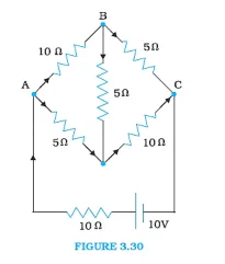
Solution: The current flowing through different branches of the circuit is shown in the figure Provided
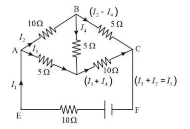
$I_{1}=$ Current flowing through the outer circuit
$I_{2}=$ Current flowing through branch $\mathrm{AB}$
$I_{3}=$ Current flowing through branch $\mathrm{AD}$
$I_{2}-I_{4}=$ Current flowing through branch $\mathrm{BC}$
$I_{3}+I_{4}=$ Current flowing through branch DC
$I_{4}=$ Current flowing through branch BD
For the closed circuit ABDA, the potential drop is zero, i.e.,
$10 I_{2}+5 I_{4}-5 I_{3}=0$
$\Rightarrow 2 I_{2}+I_{4}-I_{3}=0$
$\Rightarrow I_{3}=2 I_{2}+I_{4} \ldots$ (1)
For the closed circuit BCDB, the potential drop is zero, i.e.,
$5\left(I_{2}-I_{4}\right)-10\left(I_{3}+I_{4}\right)-5 I_{4}=0$
$\Rightarrow 5 I_{2}+5 I_{4}-10 I_{3}-10 I_{4}-5 I_{4}=0$
$\Rightarrow 5 I_{2}-10 I_{3}-20 I_{4}=0$
$\Rightarrow I_{2}=2 I_{3}+4 I_{4} \ldots$... (2)
For the closed circuit ABCFEA, the potential drop is zero, i.e.,
$-10+10\left(I_{1}\right)+10\left(I_{2}\right)+5\left(I_{2}-I_{4}\right)=0$
$\Rightarrow 10=15 I_{2}+10 I_{1}-5 I_{4}$
$\Rightarrow 3 I_{2}+2 I_{1}-I_{4}=2 \ldots(3)$
From equations (1) and (2), we obtain
$I_{3}=2\left(2 I_{3}+4 I_{4}\right)+I_{4}$
$\Rightarrow I_{3}=4 I_{3}+8 I_{4}+I_{4}$
$-3 I_{3}=9 I_{4}$
$-3 I_{4}=+I_{3} \ldots(4)$
Putting equation (4) in equation (1), we can obtain
$I_{3}=2 I_{2}+I_{4}$
$\Rightarrow-4 I_{4}=2 I_{2}$
$\Rightarrow I_{2}=-2 I_{4} \ldots(5)$
From the given figure,
$I_{1}=I_{3}+I_{2} \ldots$ (6)
From equation (6) and equation (1), we obtain
$3 I_{2}+2\left(I_{3}+I_{2}\right)-I_{4}=2$
$\Rightarrow 5 I_{2}+2 I_{3}-I_{4}=2 \ldots(7)$
$\Rightarrow 5\left(-2 I_{4}\right)+2\left(-3 I_{4}\right)-I_{4}=2$
$\Rightarrow-10 I_{4}-6 I_{4}-I_{4}=2$
$17 I_{4}=-2$
$I_{4}=\frac{-2}{17} A$
Equation (4) reduces to
$I_{3}=-3\left(I_{4}\right)$
$=-3\left(\frac{-2}{17}\right)=\frac{6}{17} \mathrm{~A}$
$I_{2}=-2\left(I_{4}\right)$
$=-2\left(\frac{-2}{17}\right)=\frac{4}{17} A$
$I_{2}-I_{4}=\frac{4}{17}-\left(\frac{-2}{17}\right)=\frac{6}{17} \mathrm{~A}$
$I_{3}+I_{4}=\frac{6}{17}+\left(\frac{-2}{17}\right)=\frac{4}{17} \mathrm{~A}$
$I_{1}=I_{3}+I_{2}$
$=\frac{6}{17}+\frac{4}{17}=\frac{10}{17} \mathrm{~A}$
Therefore, current in branch $A B=\frac{4}{17} \mathrm{~A}$
In branch $B C=\frac{6}{17} \mathrm{~A}$
In branch $C D=\frac{-4}{17} A$
In branch $A D=\frac{6}{17} \mathrm{~A}$
In branch $B D=\frac{-2}{17} \mathrm{~A}$
Total current $=\frac{4}{17}+\frac{6}{17}+\frac{-4}{17}+\frac{6}{17}+\frac{-2}{17}=\frac{10}{17} \mathrm{~A}$
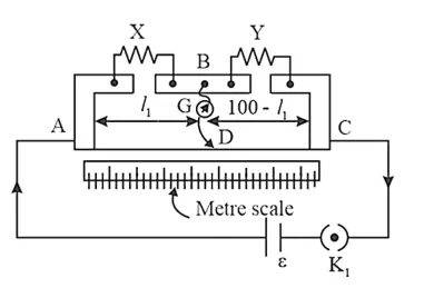
Question 10. (a) In a meter bridge [Fig. $3.27]$, the balance point is found to be at $39.5 \mathrm{~cm}$ from the end $\mathrm{A}$ when the resistor $\mathrm{Y}$ is of $12.5 \Omega$. Determine the resistance of $X$. Why are the connections between resistors in a Wheatstone or meter bridge made of thick copper strips? (b) Determine the balance point of the bridge above if $\mathrm{X}$ and $\mathrm{Y}$ are interchanged.
(c) What happens if the galvanometer and cell are interchanged at the balance point of the bridge? Would the galvanometer show any current?
Solution. The figure shows a meter bridge with resistors $\mathrm{X}$ and $\mathrm{Y}$.
(a) Balance point from end $A, I_{1}$ is $39.5 \mathrm{~cm}$
The Resistance of the resistor $Y$ is $12.5 \Omega$
Condition for the balance is given as,
$\frac{X}{Y}=\frac{100-l_{1}}{l_{1}}$
$X=\frac{100-39.5}{39.5} \times 12.5=8.2 \Omega$
The resistance of resistor $X$ is $8.2 \Omega$.
The thick copper strips which are used in a Wheat stone bridge is used to minimize the resistance of connecting wires
(b) If $X$ and $Y$ are interchanged, then $l_{1}$ and $100-l_{1}$ get interchanged.
The balance point of the bridge is $100-l_{1}$ from $A$.
$100-l_{1}=100-39.5=60.5 \mathrm{~cm}$
The balance point is $60.5 \mathrm{~cm}$ from $\mathrm{A}$.
(c) The galvanometer will show no deflection when the galvanometer and cell are interchanged at the balance point. Therefore, no current would flow through the galvanometer.
Question 11. A storage battery of emf $8.0 \mathrm{~V}$ and internal resistance $0.5 \Omega$ is being charged by a $120 \mathrm{~V}$ DC supply using a series resistor of $15.5 \Omega$.
What is the terminal voltage of the battery during charging? What is the purpose of having a series resistor in the charging circuit?
Solution. Given:
Emf of the storage battery, $E$, is $8.0 \mathrm{~V}$
The Internal resistance of the battery, $r$, is $0.5 \Omega$
$D C$ supply voltage, $V$ is $120 \mathrm{~V}$
The Resistance of the resistor, $R$, is $15.5 \Omega$
Effective voltage in the circuit $=V^{\prime}$
$\mathrm{R}$ is connected in series to the storage battery. It can therefore be written as
$V^{\prime}=V-E$
$\Rightarrow V^{\prime}=120-8=112 \mathrm{~V}$
Current flowing in the cireuit $=I$, which is given by the relation, Reference the sentence
$I=\frac{V^{\prime}}{R+r}$
$=\frac{112}{15.5+5}=\frac{112}{16}=7 \mathrm{~A}$
The Voltage across resistor $\mathrm{R}$ given by the product, $I R=7 \times 15.5=108.5 \mathrm{~V}$
$D C$ voltage supply $=$ Voltage drop across $\mathrm{R}+$ Terminal voltage of the battery
The terminal voltage of battery $=120-108.5=11.5 \mathrm{~V}$
The Current will be very large in the absence of a series resistor in a charging circuit. The Work of a series resistor in a charging circuit is to reduce the amount of current drawn from the external circuit.
Question 12. In a potentiometer arrangement, a cell of emf $1.25 \mathrm{~V}$ gives a balance point at $35.0 \mathrm{~cm}$ length of the wire. If the cell is replaced by another cell and the balance point shifts to $63.0 \mathrm{~cm}$, what is the emf of the second cell?
Solution. Given:
Emf of the cell, $E_{1}$ is $1.25 \mathrm{~V}$
The Balance point of the potentiometer, $l_{1}$ is $35 \mathrm{~cm}$
The cell is substituted by another cell of $\mathrm{emf} E_{2}$
The new balance point of the potentiometer, $l_{2}$ is $63 \mathrm{~cm}$
The balance condition is given by the relationship,
$\frac{E_{1}}{E_{2}}=\frac{l_{1}}{l_{2}}$
$E_{2}=E_{1} \times \frac{l_{2}}{l_{1}}$
$=1.25 \times \frac{63}{35}=2.25 \mathrm{~V}$
Emf of the second cell is $2.25 \mathrm{~V}$.
Question 13. The number density of free electrons in a copper conductor estimated in Example $3.1$ is $8.5 \times 10^{28} \mathrm{~m}^{-3}$. How long does an electron take to drift from one end of a wire $3.0 \mathrm{~m}$ long to its other end? The area of cross-section of the wire is $2.0 \times 10^{-6} \mathrm{~m}^{2}$ and it is carrying a current of $3.0 \mathrm{~A}$.
Solution. Given:
The number density in a copper conductor of free electrons, $n$ is $8.5 \times 10^{28} \mathrm{~m}^{-3}$
Length of the copper wire, $I$ is $3.0 \mathrm{~m}$
Area of a cross-section of the wire, $A$ is $2.0 \times 10^{-6} \mathrm{~m}^{2}$
The Current carried by the wire, $I=3.0 \mathrm{~A}$,
$I=n A e V_{d}$
Where,
$\mathrm{e}=$ Electric charge $=1.6 \times 10^{-19} \mathrm{C}$
$V_{d}=$ Drift velocity $=\frac{\text { Length of the wire }(l)}{\text { Time taken to cover }(\mathrm{t})}$
$I=n A e \frac{l}{t}$
$t=\frac{n A e l}{I}$
$=\frac{3 \times 8.5 \times 10^{28} \times 2 \times 10^{-6} \times 1.6 \times 10^{-19}}{3.0}$
$=2.7 \times 10^{4} \mathrm{~s}$
The Time taken by an electron to drift from one end of the wire to the other is given by $2.7 \times 10^{4} \mathrm{~s}$
Question 14. The earth's surface has a negative surface charge density of $10^{-9} \mathrm{C} \mathrm{m}^{-2}$. The potential difference of $400 \mathrm{kV}$ between the top of the atmosphere and the surface results (due to the low conductivity of the lower atmosphere) in a current of only 1800 A over the entire globe. If there were no mechanism of sustaining atmospheric electric field, how much time (roughly) would be required to neutralise the earth's surface? (This never happens in practice because there is a mechanism to replenish electric charges, namely the continual thunderstorms and lightning in different parts of the globe). (Radius of earth $=6.37 \times 10^{6} \mathrm{~m}$.)
Solution. Given:
The Surface charge density of the earth $(\sigma)$ is $10^{-9} \mathrm{C} \mathrm{m}^{-2}$
The Current over the entire globe $(I)$ is $1800 \mathrm{~A}$
The Radius of the earth $(r)$ is $6.37 \times 10^{6} \mathrm{~m}$
The Surface area of the earth,
$A=4 n r^{2}$
$=4 \Pi \times\left(6.37 \times 10^{6}\right)^{2}$
$=5.09 \times 10^{14} \mathrm{~m}^{2}$
Charge on the earth surface,
$q=\sigma \times A$
$=10^{-9} \times 5.09 \times 10^{14}$
$=5.09 \times 10^{5} \mathrm{C}$
Time taken to neutralize the earth's surface $=t$
Current, $I=\frac{q}{t}$
$t=\frac{q}{I}$
$=\frac{5.09 \times 10^{5}}{1800}=282.77 \mathrm{~s}$
The Time taken to neutralize the earth's surface is $282.77 \mathrm{~s}$.
Question 15. (a) Six lead-acid type of secondary cells each of emf $2.0 \mathrm{~V}$ and internal resistance $0.015 \Omega$ are joined in series to provide a supply to the resistance of $8.5 \Omega$. What is the current drawn from the supply and its terminal voltage?
(b) A secondary cell after long use has an emf of $1.9 \mathrm{~V}$ and a large internal resistance of $380 \Omega$. What maximum current can be drawn from the cell? Could the cell drive the starting motor of a car?
Solution: Given:
(a) $\quad$ Number of secondary cells, $n$ is 6
Emf of each secondary cell, $E$ is $2.0 \mathrm{~V}$
The internal resistance of each cell, $r$ is $0.015 \Omega$
The Series resistor is connected to the combination of cells.
The Resistance of the resistor, $R$ is $8.5 \Omega$
Current drawn from the supply $=I$, which is given by the relation,
$I=\frac{n E}{R+n r}$
$=\frac{6 \times 2}{8.5+6 \times 0.015}$ $=\frac{12}{8.59}=1.39 \mathrm{~A}$
Terminal voltage, $V=I R=1.39 \times 8.5=11.87 \mathrm{~A}$
A current of $1.39 \mathrm{~A}$, is drawn from the supply and the terminal voltage is $11.87 \mathrm{~A} .$
(b) After a long use, emf of the secondary cell, $E$ is $1.9 \mathrm{~V}$
The Internal resistance of the cell, $r$ is $380 \Omega$
A maximum current of $0.005 \mathrm{~A}$ can be drawn from the cell.
Since a large current is required to start the motor of a car, it is not possible to use the cell to start a motor.
Question 16. Two wires of equal length, one of aluminium and the other of copper, have the same resistance. Which of the two wires is lighter? Hence explain why aluminium wires are preferred for overhead power cables $\left(\rho_{\mathrm{Al}}=2.63 \times 10^{-8} \Omega \mathrm{m}, \quad \rho_{\mathrm{Cu}}=\right.$ $1.72 \times 10^{-8} \Omega \mathrm{m}$, Relative density of $\mathrm{Al}=2.7$, of $\mathrm{Cu}=8.9$ )
Solution. Given:
Resistivity of aluminium $\rho_{A l}$ is $2.63 \times 10^{-8} \Omega \mathrm{m}$
The Relative density of aluminium, $d_{1}$, is $2.7$
Let $l_{1}$ be the length of aluminium wire and $m_{1}$ be its mass.
The Resistance of the aluminium wire is $R_{1}$
Area of a cross-section of the aluminium wire is $A_{1}$
The Resistivity of copper, $\rho_{C u}=1.72 \times 10^{-8} \Omega \mathrm{m}$
Let $l_{2}$ be the length of copper wire and $m_{2}$ be its mass.
The Resistance of the copper wire is $R_{2}$
Area of the cross-section of the copper wire is $A_{2}$
The two relations can be written as
$R_{1}=\rho_{1} \frac{l_{1}}{A_{1}}$$\ldots(1)$
$R_{2}=\rho_{2} \frac{l_{2}}{A_{2}}$...(2)
It is given that $R_{1}=R_{2} \Rightarrow \rho_{1} \frac{l_{1}}{A_{1}}=\rho_{2} \frac{l_{2}}{A_{2}}$
$\Rightarrow \frac{A_{1}}{A_{2}}=\frac{\rho_{1}}{\rho_{2}}=\frac{2.63 \times 10^{-8}}{1.72 \times 10^{-8}}=\frac{2.63}{1.72}$
Mass of the aluminium wire, $m_{1}=$ volume $\times$ Density
$A_{1} l_{1} \times d_{1}=A_{1} l_{1} d_{1}$ (3)
Mass of the copper wire, $m_{2}=$ volume $\times$ Density
$A_{2} l_{2} \times d_{2}=A_{2} l_{2} d_{2}(4)$
By Dividing equation (3) by equation (4), we obtain
$\frac{m_{1}}{m_{2}}=\frac{A_{1} l_{1} d_{1}}{A_{2} l_{2} d_{2}}$
For $l_{1}=l_{2}$
$\frac{m_{1}}{m_{2}}=\frac{A_{1} d_{1}}{A_{2} d_{2}}$
For $\frac{A_{1}}{A_{2}}=\frac{2.63}{1.72}$
$\frac{m_{1}}{m_{2}}=\frac{2.63}{1.72} \times \frac{2.7}{8.9}=0.46$
It can be inferred from this ratio that $m_{1}$ is less than $m_{2}$. Hence, aluminium is lighter than copper. Because aluminium is lighter, it is preferred for overhead power cables over copper.
Question 17. What conclusion can you draw from the following observations on a resistor made of alloy manganin?
Solution.
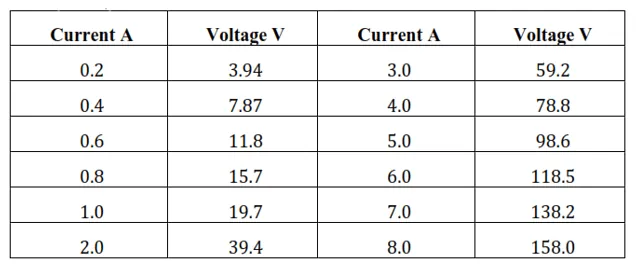
From the given table, it can be inferred that the voltage-to-current ratio is a constant equal to 19.7. Therefore, manganin is an ohmic conductor, i.e., the alloy obeys Ohm's law. According to Ohm's law, the conductor's resistance is the voltage proportion with the current. Therefore, manganin's resistance is $19.7 \Omega$.
Question 18. Answer the following questions:
Solution. (a) A steady current flow in a metallic conductor of non - uniform crosssection. Which of these qualities is constant along the conductor: Current, Current density, electric field, drift speed?
(b) Is Ohm's law is universally applicable for all conducting elements?
(c) A low voltage supply from which one needs high currents must have very low internal resistance. Why?
(d) A high tension (HT) Supply of, say, $6 \mathrm{KV}$ must have a very large internal resistance. Why?
Solution: (a) Current density, drift speed and electric field are inversely proportional to the area of cross section, and hence, they are not constant. The current flowing through the conductor is constant when a steady current flow in a metallic conductor of the non-uniform cross-section.
(b) Ohm's law cannot be applied universally to all conducting elements. Ohm's law is not applicable for Vacuum diode semiconductor.
(c) By Ohm's law, the relation for the potential is $V=I R$
Voltage $(V)$ is directly proportional to the Current (I).
$R$ is the internal resistance of the source.
$I=\frac{V}{R}$
If $V$ is low, then $R$ must be very low, so that high current can be drawn from the source.
(d) To prevent the electrical current from exceeding the safety threshold, a high tension supply must have a very high internal resistance. If the internal resistance is not high, the current drawn may exceed the safety limits in the case of a short circuit.
Question 19. Choose the correct alternative:
(a) Alloys of metals usually have (greater/less) resistivity than that of their constituent metals.
(b) Alloys usually have much (lower/higher) temperature coefficients of resistance than pure metals.
(c) The resistivity of the alloy manganin is nearly independent of/increases rapidly with the increase of temperature.
(d) The resistivity of a typical insulator (e.g., amber) is greater than that of a metal by a factor of the order of $\left(10^{22} / 10^{33}\right)$.
Solution: (a) Alloys of metals usually have greater resistivity than that of their constituent metals.
(b) Alloys usually have lower temperature coefficients of resistance than pure metals.
(c) The resistivity of the alloy, manganin is nearly independent of increase of temperature.
(d) The resistivity of a typical insulator is greater than that of a metal by a factor of the order of $10^{22}$.
Question 20. (a) Given $n$ resistors each of resistance $R$, how will you combine them to get the (i) maximum (ii) minimum effective resistance? What is the ratio of the maximum to minimum resistance?
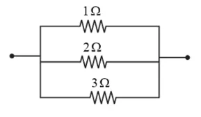
(b) Given the resistances of $1 \Omega, 2 \Omega, 3 \Omega$, how will you combine them to get an equivalent resistance of (i) $(11 / 3) \Omega$ (ii) $(11 / 5) \Omega$, (iii) $6 \Omega$, (iv) $(6 / 11) \Omega ?$
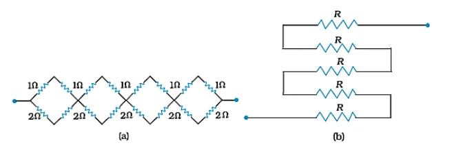
(c) Determine the equivalent resistance of networks shown in Fig.
Solution: Given:
(a) $\quad$ Total number of resistors $=n$
The resistance of each resistor $=R$
(i) The effective resistance $R_{1}$ maximum when $\mathrm{n}$ resistors are connected in series, given by the product $n R$.
Hence, maximum resistance of the combination, $R_{1}=n R$
(ii) When $n$ resistors are connected in parallel, the effective resistance $\left(R_{2}\right)$ is the minimum, given by the ratio $\frac{R}{n}$
Hence, minimum resistance of the combination, $R_{2}=\frac{R}{n}$
(iii) The ratio of the maximum to the minimum resistance is,
$\frac{R_{1}}{R_{2}}=\frac{n R}{\frac{R}{n}}=n^{2}$
(b) The resistance of the given resistors is,
$R_{1}=1 \Omega, R_{2}=2 \Omega, R_{3}=3 \Omega$
(i) Equivalent resistance, $R^{\prime}=\frac{11}{3} \Omega$
Considering the following combination of the resistors.
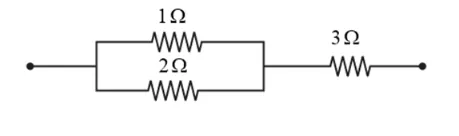
The Equivalent resistance of the circuit is given by,
$R^{\prime}=\frac{2 \times 1}{2+1}+3=\frac{2}{3}+3=\frac{11}{3} \Omega$
(ii) Equivalent resistance, $R^{\prime}=\frac{11}{5} \Omega$
Considering the following combination of the resistors.
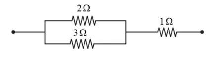
The Equivalent resistance of the circuit is given by,
$R^{\prime}=\frac{2 \times 3}{2+3}+1=\frac{6}{5}+1=\frac{11}{5} \Omega$
(iii) Equivalent resistance, $R^{\prime}=6 \Omega$
The series combination of the resistors is as shown in the given circuit.
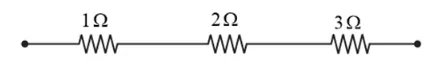
The Equivalent resistance of the circuit is given by the sum,
$R^{\prime}=1+2+3=6 \Omega$
(iv) Equivalent resistance, $R^{\prime}=\frac{6}{11} \Omega$
Considering the series combination of the resistors, as shown in the given circuit.
The Equivalent resistance of the circuit is given by,
$R^{\prime}=\frac{1 \times 2 \times 3}{1 \times+2 \times 3+3 \times 1}=\frac{6}{11} \Omega$
(c) It can be observed from the given circuit that in the first small loop, two resistors of resistance $1 \Omega$ each are connected in series.
Hence, their equivalent resistance $=(1+1)=2 \Omega$
Therefore, the circuit can be redrawn as
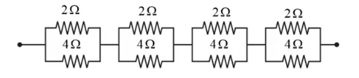
It can be observed that $2 \Omega$ and $4 \Omega$ resistors are connected in parallel in all the four loops.
Hence, the equivalent resistance $\left(R^{\prime}\right)$ of each loop is given by,
$R^{\prime}=\frac{2 \times 4}{2+4}=\frac{8}{6}=\frac{4}{3} \Omega$
The circuit reduces to.
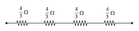
All the four resistors are connected in series.
Hence, the equivalent resistance of the given circuit is $\frac{4}{3} \times 4=\frac{16}{3} \Omega$
(b) The five resistors of resistance $R$ each are connected in series hence, the equivalent resistance of the circuit $=R+R+R+R+R=5 R$
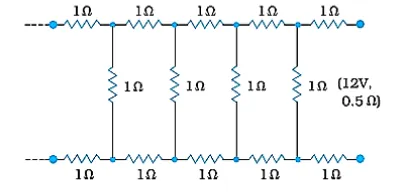
Question 21. Determine the current drawn from a $12 \mathrm{~V}$ supply with internal resistance $0.5 \Omega$ by the infinite network shown in Fig. Each resistor has $1 \Omega$ resistance.
Solution. Given:
The resistance of each resistor connected in the circuit, $R$ is $1 \Omega$
Let the equivalent resistance of the given circuit is $R^{\prime}$ and the network is infinite.
Hence, the equivalent resistance is given by the relation,
$R^{\prime}=2+\frac{R^{\prime}}{\left(R^{\prime}+1\right)}$
$\Rightarrow\left(R^{\prime}\right)^{2}-2 R^{\prime}-2=0$
$R^{\prime}=\frac{2 \pm \sqrt{4+8}}{2} \Omega$
$=\frac{2 \pm \sqrt{12}}{2}=(1 \pm \sqrt{3}) \Omega$
Negative value of $R^{\prime}$ cannot be accepted.
Hence, equivalent resistance,
$R^{\prime}=(1+\sqrt{3}) \Omega=(1+1.73) \Omega=2.73 \Omega$
The Internal resistance of the circuit,
$r=0.5 \Omega$
The total resistance of the given circuit is given by
$=2.73+0.5=3.23 \Omega$
Supply voltage, $V=12 \mathrm{~V}$
Current drawn from the source is given according, to Ohm's law by $\frac{12}{3.23}=3.72 \mathrm{~A}$
Question 22. The figure shows a potentiometer with a cell of $2.0 \mathrm{~V}$ and internal resistance $0.40 \Omega$ maintaining a potential drop across the resistor wire AB. A standard cell which maintains a constant emf of $1.02 \mathrm{~V}$ (for very moderate currents up to a few $\mathrm{mA}$ ) gives a balance point at $67.3 \mathrm{~cm}$ length of the wire. To ensure very low currents drawn from the standard cell, very high resistance of $600 \mathrm{k} \Omega$ is put in series with it, which is shorted close to the balance point. The standard cell is then replaced by a cell of unknown emf $\varepsilon$, and the balance point found similarly, turns out to be at $82.3 \mathrm{~cm}$ length of the wire.
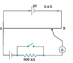
(a) What is the value $\varepsilon$ ?
(b) What purpose does the high resistance of $600 \mathrm{k} \Omega$ have?
(c) Is the balance point affected by this high resistance?
(d) Is the balance point affected by the internal resistance of the driver cell?
(e) Would the method work in the above situation if the driver cell of the potentiometer had an emf of $1.0 \mathrm{~V}$ instead of $2.0 \mathrm{~V} ?$
(f) Would the circuit work well for determining an extremely small emf, say of the order of a few $\mathrm{mV}$ (such as the typical emf of a thermocouple)? If not, how will you modify the circuit?
Solution. Given:
(a) A Constant emf of the given standard cell, $E_{1}$ is $1.02 \mathrm{~V}$
The Balance point on the wire, $l_{1}$ is $67.3 \mathrm{~cm}$
The standard cell is replaced by a cell of unknown emf, $\varepsilon$
$\therefore$ The new balance point on the wire, $l$ is $82.3 \mathrm{~cm}$
The relation connecting balance point and emf is,
$\frac{E_{1}}{l_{1}}=\frac{\varepsilon}{l}$
$\varepsilon=\frac{l}{l_{1}} \times E_{1}$
The value of the unknown emf is $1.247 \mathrm{~V}$.
(b) High resistance of $600 \mathrm{k} \Omega$ is used to lower the current flow through the galvanometer when the movable contact is far from the balance point.
(c) The presence of high resistance does not affect the balance point.
(d) The internal resistance of the driver cell does not affect the balance point.
(e) If the potentiometer's driver cell emf is less than the other cell's emf, then there would be no balance point on the wire, so the method won't operate, if the potentiometer's driver cell has an emf of $1 \mathrm{~V}$ instead of $2 \mathrm{~V}$.
(f) The circuit cannot work well for determining an extremely small emf as there will be a very high pereentage of error. This is because the circuit would be unstable; the balance point would be close to end $\mathrm{A}$.
If a series resistance is connected to the wire $\mathrm{AB}$, the given circuit can be modified. AB's potential drop is slightly higher than the measured emf. It would be a small percentage error.
Question 23. The figure shows a $2.0 \mathrm{~V}$ potentiometer used for the determination of internal resistance of a $1.5 \mathrm{~V}$ cell. The balance point of the cell in open circuit is $76.3 \mathrm{~cm}$. When a resistor of $9.5 \Omega$ is used in the external circuit of the cell, the balance point shifts to $64.8 \mathrm{~cm}$ length of the potentiometer wire. Determine the internal resistance of the cell.
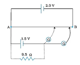
Solution. Given:
The internal resistance of the cell is $\mathrm{r}$
The balance point of the cell in the open circuit, $l_{1}$ is $76.3 \mathrm{~cm}$
An external resistance of resistance $\mathrm{R}=9.5 \Omega$ is connected to the circuit.
The new balance point of the circuit, $l_{2}$ is $64.8 \mathrm{~cm}$
The current $(I)$ flowing through the circuit is
The relation between emf and resistance is,
$r=\left(\frac{l_{1}-l_{2}}{l_{2}}\right) R$
$=\frac{76.3 \mathrm{~cm}-64.8 \mathrm{~cm}}{64.8 \mathrm{~cm}} \times 9.5 \Omega=1.68 \Omega$
The internal resistance of the cell is $1.68 \Omega$.
Also Read,
Class 12 Physics Notes Free PDF Download.
Class 12 Physics Book Chapterwise Free PDF Download.
Class 11 Physics Exemplar Chapterwise Free PDF Download.
If you have any Confusion related to NCERT Solutions for Class 12 Physics Chapter 3 Current Electricity PDF then feel free to ask in the comments section down below.
To watch Free Learning Videos on Class 12 Physics by Kota’s top IITan’s Faculties Install the eSaral App