Ammeter and Voltmeter Circuit Diagram | Current Electricity Class 12, JEE & NEET

Home > Current Electricity Class 12 > Ammeter and Voltmeter Circuit Diagram

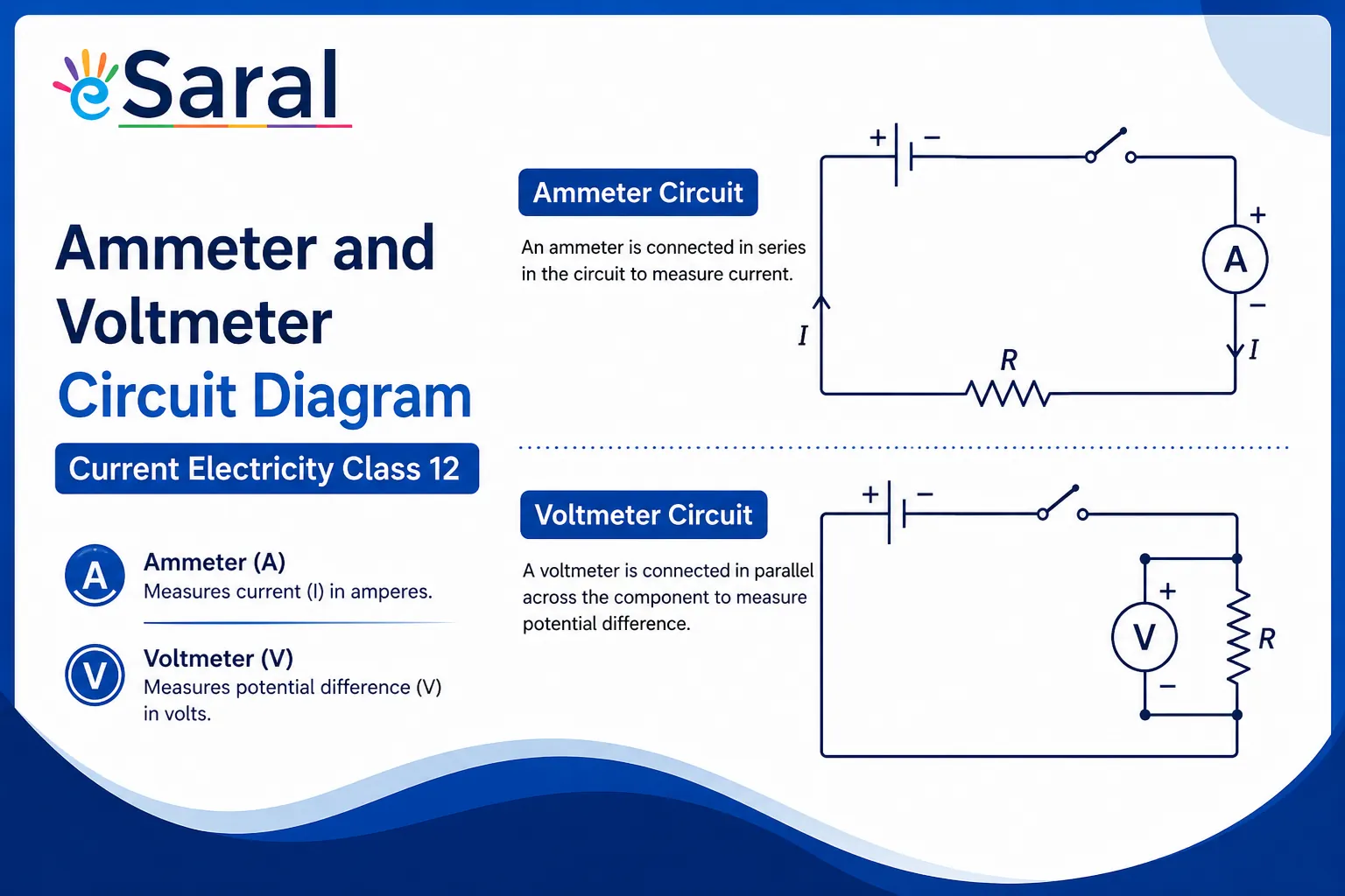
Voltmeters and ammeters are used to measure voltage and current, respectively. Here, we will discuss both the Ammeter and Voltmeter Circuit Diagram.
India's Best Exam Preparation for Class 12th - Download Now
In current electricity, two instruments appear in almost every circuit diagram — the ammeter and the voltmeter. Understanding how they work, how they are constructed from a galvanometer, and where they are placed in a circuit is a high-weightage topic in Class 12 Physics (CBSE), JEE Main, and NEET.
The NTA consistently tests this concept — questions on shunt resistance calculation, galvanometer conversion, and the effect of meter resistance on circuit readings appear every year in both JEE Main and NEET papers.
This article covers the complete theory behind ammeter and voltmeter circuit diagrams, the derivation of shunt and series resistance formulas, a comparison table, and a fully solved numerical example. For deeper NCERT-aligned practice, explore the NCERT Solutions for Class 12 Physics prepared by eSaral's IIT Bombay faculty.
Ammeter — Working, Circuit Diagram & Formulas
An ammeter is a low-resistance galvanometer used to measure the strength of current flowing through an electrical circuit. Because current measurement requires the instrument to be part of the current path, an ammeter is always connected in series.
Key properties of an ammeter:
- Ideal resistance: Zero (so it does not alter the circuit's current)
- Practical resistance: Very small but finite (causes slight underreading)
- Connection: Always in series
- Accuracy rule: Lower the resistance of the ammeter → more accurate the reading
How Does an Ammeter Work in a Circuit?
When connected in series, an ammeter carries the full current of the branch being measured. If its resistance were significant, it would reduce the current and give a false reading. This is why the shunt (a low resistance) is added in parallel to the galvanometer coil — most of the current bypasses the sensitive coil through the shunt, protecting the galvanometer while still allowing measurement.
Ammeter Circuit Diagram:
The galvanometer (resistance G) and shunt (resistance S) are connected in parallel. The current I entering splits: Ig flows through the galvanometer, and (I − Ig) flows through the shunt.
        ┌──── G (galvanometer) ────┐
I ──────┤                          ├────── I
        └──── S (shunt)           ─┘
Shunt Resistance — Formula and Derivation
Since G and S are in parallel, the voltage across both is equal:
$$I_g \cdot G = (I - I_g) \cdot S$$
$$\boxed{S = \frac{I_g \cdot G}{I - I_g}}$$
Resistance of the converted ammeter:
$$R_A = \frac{G \cdot S}{G + S}$$
Increasing the range N times:
If the new full-scale current $I = N \cdot I_g$, the required shunt is:
$$S = \frac{G}{N - 1}$$
Reducing shunt resistance increases the range of the ammeter but decreases its sensitivity. This is the fundamental trade-off every JEE student must know.
Length of shunt wire required:
$$\ell = \frac{\pi r^2 S}{\rho}$$
where r = radius of shunt wire and ρ = resistivity of the shunt material.
In JEE problems, students often confuse which device uses a parallel connection and which uses a series connection. Remember: Ammeter → Addition to current path → series. Voltmeter → Very high R → parallel. This mnemonic has helped hundreds of eSaral students avoid this common 1-mark error.
Voltmeter — Working, Circuit Diagram & Formulas
A voltmeter is a high-resistance galvanometer used to measure the potential difference (voltage) between two points in a circuit.
Key properties of a voltmeter:
- Ideal resistance: Infinite (draws zero current from the circuit)
- Practical resistance: Very large but finite (causes slight underreading)
- Connection: Always in parallel
- Accuracy rule: The higher the resistance of the voltmeter → more accurate the reading
How is a Voltmeter Connected and Why?
A voltmeter is connected in parallel with the circuit element across which you want to measure voltage. If it were connected in series, it would block most of the current (due to its high resistance) and destroy the circuit's normal operation. When connected in parallel, it draws negligible current, so the potential difference being measured remains virtually unchanged.
Voltmeter Circuit Diagram:
A high resistance R is connected in series with the galvanometer coil (resistance G):
V ──── [R (series)] ──── [G (galvanometer)] ──── V
Series Resistance Formula for Voltmeter
The voltage across the voltmeter equals the full-scale deflection current times the total resistance:
$$V = I_g (R + G)$$
$$\boxed{R = \frac{V}{I_g} - G}$$
Resistance of the converted voltmeter:
$$R_V = R + G$$
Increasing the range N times:
If new range $V = N \cdot V_0 = N \cdot I_g \cdot G$, then:
$$R = (N - 1)G$$
The series resistance must be increased to increase the voltmeter range. Unlike the ammeter, this does not reduce sensitivity — it actually maintains accuracy by keeping the galvanometer current controlled.
A question that frequently appears in NEET: "Why does a voltmeter read slightly less than the actual potential difference?" The answer is that even a high-resistance voltmeter draws a small current, slightly loading the circuit and dropping its terminal voltage. In our Kota-quality online batches at eSaral, we solve 15+ such conceptual traps before each mock test to build examination reflexes — not just formula recall.
Ammeter vs Voltmeter — Key Differences
| Feature | Ammeter | Voltmeter |
|---|---|---|
| Measures | Current (A) | Potential difference (V) |
| Connected | In series | In parallel |
| Resistance | Very low (ideally 0) | Very high (ideally ∞) |
| Galvanometer conversion | Low shunt in parallel | High resistance in series |
| Effect of non-ideal resistance | Reduces measured current | Reduces measured voltage |
| Range increased by | Decreasing shunt S | Increasing series R |
| Sensitivity affected by range increase? | Yes, reduced | No significant change |
| Symbol in circuit | ⓐ (circle with A) | ⓥ (circle with V) |
For complete NCERT-aligned notes on this chapter, refer to the NCERT Solutions for Class 12 Physics and the NCERT Books for Class 12 available on eSaral.
Solved Example
Question: What is the value of the shunt that passes 10% of the main current through a galvanometer of 99 Ω?
Solution:
Given: $I_g = \frac{10}{100} I = 0.1I$, $G = 99\ \Omega$
Using the shunt formula:
$$S = \frac{I_g \cdot G}{I - I_g} = \frac{0.1I \times 99}{I - 0.1I} = \frac{9.9I}{0.9I} = \frac{9.9}{0.9}$$
$$\boxed{S = 11\ \Omega}$$
Interpretation: A shunt of 11 Ω allows 90% of the current to bypass the galvanometer, protecting it while still enabling current measurement.
Also Read:
- Types and Effects of Electric Current
- Ohm’s Law and Resistance
- Combination of Resistances
- EMF and Internal Resistances of a Cell
- Cells Connected in Series, Parallel, and Mixed
- Kirchhoff’s Circuit Law
- Electric Currents in Conductors
- Wheatstone Bridge
- Post Office Box
- Wheatstone Meter Bridge
- Moving Coil Galvanometer
- Ammeter and Voltmeter
- Potentiometer Working Principle
Frequently Asked Questions
Find answers to common questions.
How is a galvanometer converted into an ammeter?
A galvanometer is converted into an ammeter by connecting a low resistance shunt in parallel with the galvanometer coil. The shunt value is calculated using $S = I_g G / (I - I_g)$. The shunt diverts most of the current away from the sensitive galvanometer, extending its measurable current range without burning the coil.
Why is an ammeter always connected in series?
An ammeter is connected in series so that the full circuit current passes through it for accurate measurement. If connected in parallel, its very low resistance would short-circuit the branch, drawing excessive current and damaging the meter. Series connection ensures the ammeter does not significantly alter the total circuit resistance
What is the difference between an ammeter and a voltmeter?
An ammeter measures electric current and is connected in series with very low resistance. A voltmeter measures potential difference and is connected in parallel with very high resistance. The key distinction is their placement and resistance values — an ideal ammeter has zero resistance, while an ideal voltmeter has infinite resistance.
Why does increasing the shunt range decrease ammeter sensitivity?
Sensitivity of an ammeter refers to the deflection per unit current. When shunt resistance is reduced to increase range, a smaller fraction of the total current passes through the galvanometer for the same total current change. This means the galvanometer deflects less per ampere of main current — hence sensitivity decreases as range increases.
What happens if a voltmeter is connected in series?
If a voltmeter is connected in series, its very high resistance severely restricts current flow in the circuit, making normal circuit operation impossible. The voltmeter would show a reading close to the full supply voltage (since almost all voltage drops across it), but the circuit element being studied would effectively stop functioning. This is a common conceptual question in NEET.
How is a galvanometer converted into a voltmeter?
A galvanometer is converted into a voltmeter by connecting a high resistance in series with the galvanometer coil. The required resistance is $R = V/I_g - G$. This high series resistance limits the current through the galvanometer to its full-scale deflection value even when connected across large potential differences, enabling accurate voltage measurement.