Uses of Potentiometer | Comparison of emf of two cells using Potentiometer || Class 12, JEE & NEET
Table of Contents

The measuring instrument called a potentiometer is essentially a voltage divider used for measuring electric potential (voltage); the component is an implementation of the same principle, hence its name. Potentiometer are commonly used to control electrical devices such as volume controls on audio equipment. We will study here about Comparison of emf of two cells using Potentiometer, Determination of internal resistance of cell, Calibration of voltmeter, Calibration of ammeter, Measurement of small thermo emf.
Ex. The current flowing through the primary circuit is 2A and resistance per unit length is 0.2 $\Omega / m$. If the potential difference across 10 ohm coil is balanced at 2.5 m then find current flowing through the coil. Sol. The potential gradient $x=\frac{I R}{L}=2 \times 0.2=0.4 V / m$ Unknown potential $V=x \ell=I^{\prime} R$ so $I^{\prime}=\frac{x \ell}{R}=\frac{0.4 \times 2.5}{10}=0.1 A$
Ex. A uniform potential gradient is established across a potentiometer wire. Two cells of emf $E_{1}$ and $E_{2}$ connected to support and oppose each other are balanced over $\ell_{1}$ = 6m and $\ell_{2}$ = 2m. Find E1/E2. Sol. $E _{1}+ E _{2}= x \ell_{1}=6 x$ and $E _{1}- E _{2}=2 x$ $\frac{E_{1}+E_{2}}{E_{1}-E_{2}}=\frac{6}{2}$ or $\frac{E_{1}}{E_{2}}=\frac{2}{1}$
The Potentiometer is mainly used:
-
To compare the emfs of two primary cells
-
To determine the internal resistance of a primary cell
-
To determine the value of a high resistance
-
To determine the emf of a cell.
-
Calibration of Ammeter
-
Calibration of Voltmeter
-
measurement of small thermo emf
PRECAUTIONS IN THE USE OF POTENTIOMETER
Determination of unknown EMF or Potential Difference
- Potential gradient is found by using a standard cell $x=E_{0} / \ell_{0}$
- If unknown emf $\mathrm{E}_{1}$ is balanced at length $\ell_{1}$ then $E_{1}=x \ell_{1}=\left(\frac{E_{0}}{\ell_{0}}\right) \ell_{1}$
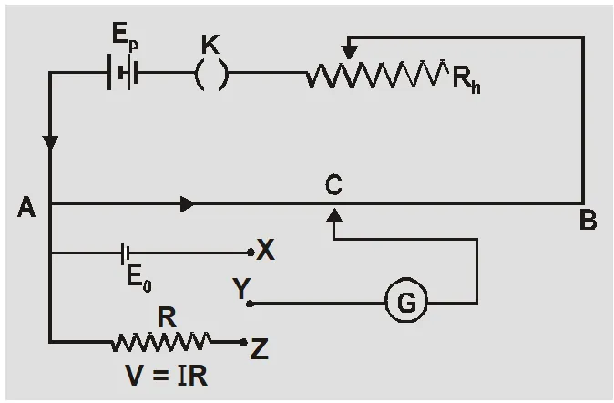
- If unknown potential difference V is balanced for length $\ell$ than $V=x \ell=\left(\frac{E_{0}}{\ell_{0}}\right) l$
- If the length of potentiometer wire is changed from L to L’ then the new balancing length is $\ell^{\prime}=\left(\frac{L^{\prime}}{L}\right) \ell$ If length is increased L’ > L so $l^{\prime}>l$ and if length is decreased L’ < L so $l^{\prime}
- If the current flowing through resistance $\mathrm{R}$ is I then $$ \mathrm{V}=\mathrm{IR}=\mathrm{x} \ell=\left(\frac{\mathrm{E}_{0}}{\ell_{0}}\right) \ell \quad \text { so } \quad \mathrm{I}=\frac{\mathrm{x} \ell}{\mathrm{R}}=\left(\frac{\mathrm{E}_{0}}{\ell_{0}}\right) \frac{\ell}{\mathrm{R}} $$
For determination of current we use a coil of standard resistance.
Ex. The current flowing through the primary circuit is 2A and resistance per unit length is 0.2 $\Omega / m$. If the potential difference across 10 ohm coil is balanced at 2.5 m then find current flowing through the coil. Sol. The potential gradient $x=\frac{I R}{L}=2 \times 0.2=0.4 V / m$ Unknown potential $V=x \ell=I^{\prime} R$ so $I^{\prime}=\frac{x \ell}{R}=\frac{0.4 \times 2.5}{10}=0.1 A$
Browse More Topics Related to Potentiometer:
- Potentiometer Working Principle
- Difference Between Potentiometer and Voltmeter
- Sensitivity of Potentiometer
- Uses of Potentiometer
- Advantages of Potentiometer
- Potentiometer Important Questions
Comparison of EMF of two cells using Potentiometer
- No standardisation is necessary.
- Let $E_{1}$ emf be balanced at length $\ell_{1}$ and $E_{2}$ emf be balanced at length $\ell_{2}$ then $E_{1}=x \ell_{1}$ and $E_{2}=x \ell_{2}$ so $\frac{E_{1}}{E_{2}}=\frac{l_{1}}{l_{2}}$
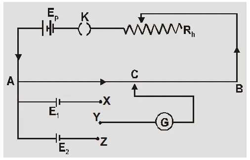
- If two cells joined in series support each other
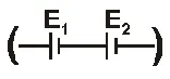 then the balancing length is $\ell_{1}$ so $E_{1}+E_{2}=x \ell_{1}$
If two cells joined in series oppose each other ![]() then the balancing length is $\ell_{2}$ so $E_{1}-E_{2}=x \ell_{2}$
then the balancing length is $\ell_{2}$ so $E_{1}-E_{2}=x \ell_{2}$
$\frac{E_{1}+E_{2}}{E_{1}-E_{2}}=\frac{\ell_{1}}{\ell_{2}}$ or $\frac{E_{1}}{E_{2}}=\frac{\ell_{1}+\ell_{2}}{\ell_{1}-\ell_{2}}$
Ex. A uniform potential gradient is established across a potentiometer wire. Two cells of emf $E_{1}$ and $E_{2}$ connected to support and oppose each other are balanced over $\ell_{1}$ = 6m and $\ell_{2}$ = 2m. Find E1/E2. Sol. $E _{1}+ E _{2}= x \ell_{1}=6 x$ and $E _{1}- E _{2}=2 x$ $\frac{E_{1}+E_{2}}{E_{1}-E_{2}}=\frac{6}{2}$ or $\frac{E_{1}}{E_{2}}=\frac{2}{1}$
Determination of Internal Resistance of Cell
- No standardization is necessary.
- Keeping $\mathrm{K}_{1}$ open the balancing length $\ell_{1}$ gives emf of cell so E = $x \ell_{1}$
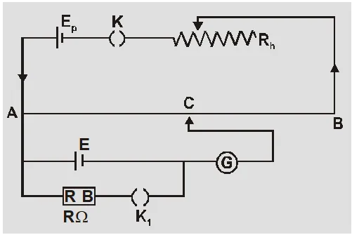
- Keeping $K_{1}$ closed the balancing length $\ell_{2}$ for some resistance R gives potential difference so V = $x \ell_{2}$
Internal resistance $r=\frac{E-V}{V} \quad R=\frac{x \ell_{1}-x \ell_{2}}{x \ell_{2}}$ $R=\left(\frac{\ell_{1}-\ell_{2}}{\ell_{2}}\right) R$
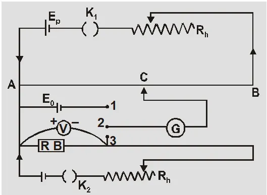
Calibration of Voltmeter
- The voltmeters do not given accurate measurements because they do not have infinite resistance.
- The error in measurement is found by comparision with readings of potentiometer.
- Potential gradient is found by using a standard cell $x=E_{0} / \ell_{0}$
- The unknown potential difference V’ is balanced at length $\ell_{1}$ then $V^{\prime}=x \ell_{1}=\frac{E_{0}}{l_{0}} \ell_{1}$
- If reading of voltmeter is V then error is V – V’ which can be positive, negative or zero.
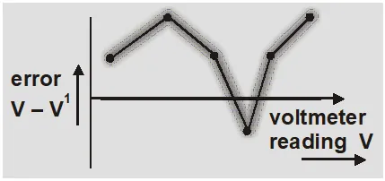
- The calibration curve is obtained plotting voltmeter reading V on x axis and error on y axis.
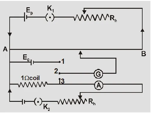
Calibration of Ammeter
- V = IR and if R = 1$\Omega$ then V = I so potential difference across 1$\Omega$ resistance is equal to current through the resistance.
- Potential gradient is found by using a standard cell $x=E_{0} / \ell_{0}$
- The current through R or 1$\Omega$ coil is measured by ammeter () and calculated by potentiometer as $V^{\prime}=I^{\prime} \times 1 \Omega=x \ell_{1}=\left(\frac{E_{0}}{\ell_{0}}\right) \ell_{1}$
- The error $I-I^{\prime}$can be found and calibration curve is obtained by plotting ammeter reading on x axis and error on y axis.
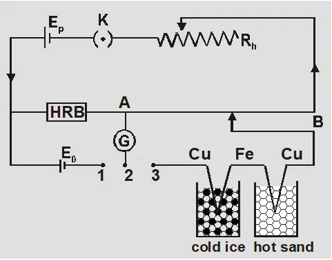
Measurement of Small Thermo EMF
- A high resistance box is used in primary circuit to reduce primary current.
- If galvanometer shows no deflection for some $R_{1}$ then potential difference across $R_{1}$ is $V=E_{0}=I R_{1}$ or $|=E_{0} / R_{1}$
- If balancing length for small thermo emf E is $\ell$ then $E=x \ell=\frac{E_{0}}{R_{1}} \cdot \frac{R}{L} \ell$
Watch out the Video: Applications of Potentiometer & its Construction by Saransh Sir.
Precautions in use of Potentiometer
- All high potential terminals of primary and secondary circuit should be connected at same point of Potentiometer.
- The known emf of primary circuit must be greater than the unknown potential difference to be measured in secondary circuit.
- The balancing length is always measured from the point of higher potential. In state of zero deflection no current flows in galvanometer circuit but it flows in primary circuit.
Complete Physics Revision Series by Saransh Sir (AIR 41 in IIT-JEE)
Also Read:
- Types and Effects of Electric Current
- Ohm’s Law and Resistance
- Combination of Resistances
- EMF and Internal Resistances of a Cell
- Cells Connected in Series, parallel and Mixed
- Kirchhoff’s Circuit Law
- Electric Currents in Conductors
- Wheatstone Bridge
- Post office Box
- Wheatstone Meter Bridge
- Moving Coil galvanometer
- Ammeter and Voltmeter